Amplifiers
Accessories
For more detailed information about a Test System for Radiated Immunity please take a look into our brochure down below.

Immunity to radiated radio-frequency electromagnetic fields acc. to:
- IEC/EN 61000-4-3
- MIL-STD 461, RS 103
- ISO 11452-2
Test devices:
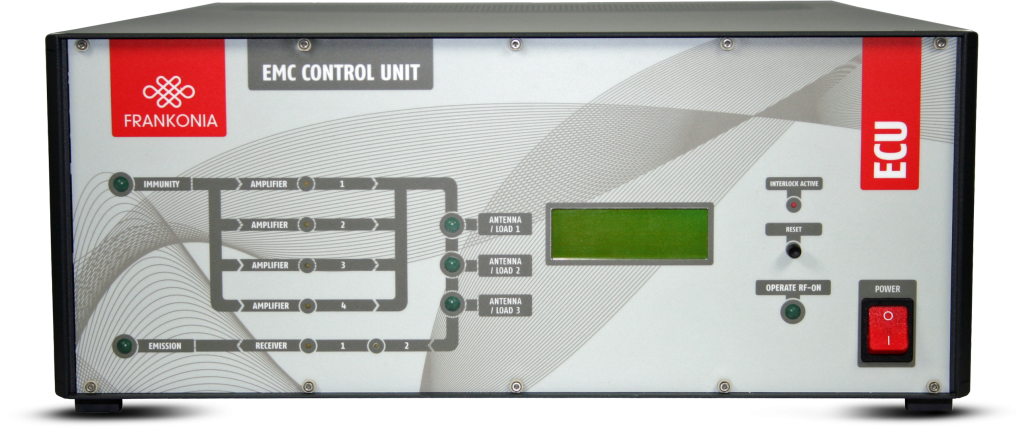
EMC Control Unit
The ECU-6 is a central EMC test and control unit, which combines in just one compact box many major test components like signal generator, power meter, directional couplers and relay switching unit, which are needed for EMC tests. That reduces the cabling work and possible cabling mistakes to a minimum. Furthermore it includes general functions like EUT-monitoring and an interlock safety-system. With all the functions described above, the ECU-6 is a real all-rounder, which can be used for many different conducted and radiated immunity tests as well as control unit to switch between EMI-receiver and spectrum analyzer and different measuring antennas without time consuming cabling work. It allows to control and to switch automatically between up to four external amplifiers, all connected to the ECU-3/-6 and up to three different outputs for antennas or coupling devices (CDNs, EM-coupling clamp, BCI-clamps). The integrated signal generator is available to cover the frequency range from 9 kHz to 6 GHz. Amplitude modulation is available with a modulation rate of 1 Hz to 30 kHz and a modulation depth of 0 % to 90 %. Pulse modulation can be switched on with a repetition frequency of 0.1 Hz to 100 kHz and a duty cycle of 1 % – 99 %. In a word, it includes all requirements according to present EMC standards and it is best prepared for possible future changes.
Special Features:
Technical specifications
| Signal Generator | ECU-6 | |
| Output | 50 Ω, N male | |
| Output (Relay) | 4 x N male | |
| Frequency range | 9 kHz to 6.5 GHz | |
| Frequency resolution | 0.001 Hz | |
| Output level range | -100 dBm to +13 dBm | |
| Output level resolution | 0.1 dB | |
| Output level accuracy | ±1 dB max. | |
| Accuracy (frequency) | ±100 ppm | |
| Harmonics | < -30 dBc | |
| Non harmonics | < -55 dBc |
| Amplitude modulation | ECU-6 | |
| Modulation rate | 1 Hz to 20 kHz; resolution 0.1 Hz | |
| Modulation depth | 0 to 90 %; resolution 1 % | |
| Modulation waveforms | sinusoidal, triangular, square |
| Pulse modulation | ECU-6 | |
| On/off ratio | typ. 80 dB | |
| Repetition frequency | 0.1 Hz to 100 kHz | |
| Duty cycle | 1%-99%; resolution1% |
| Frequency modulation | ECU-6 | |
| Modulation rate | 300 Hz to 300 kHz |
| RF-Power Meter | ECU-6 | |
| Number of channels | 9 | |
| Frequency Range | 10 kHz – 500 MHz (channel 1,2,9) 100 kHz – 6 GHz (channel 3,4,5,6,7,8) |
|
| Measuring range | -60 dBm to +20 dBm (10 kHz ≤ f ≤ 4 GHz) -45 dBm to +20 dBm (4 GHz < f ≤ 6 GHz) |
|
| Accuracy | ±1 dB (0.5 dB typical) | |
| Resolution | 0.1 dB | |
| Max. input level | +27 dBm (= 500 mW | |
| VSWR | 1.15 | |
| EUT-fail input | 2 x TTL/CMOS compatible | |
| Input resistance | 2.2 kΩ | |
| Level | TTL / CMos compatible, optical decoupled |
| EUT-monitor input | ECU-6 | |
| Input voltage (2x) | 0 – 10 V | |
| Resolution | 2.5 mV | |
| Input impedance | 100 kΩ | |
| USB-A | Multimeter (for EUT control) |
| Remote control | ECU-6 | |
| USB-B | Connection to computer | |
| GPIB / IEEE488 | Connection to computer | |
| Ethernet / RJ45 | option |
| Display | ECU-6 | |
| Displayed items | Frequency, Power levels P(forw), P(rev), modulation (4 lines x 16 characters) |
| RF-Relay Switching Unit | ECU-6 | |
| max. power up to 100 MHz | 2000W | |
| max. power up to 600 MHz | 1000W | |
| max. power up to 1 GHz | 700W | |
| max. power up to 3 GHz | 400W | |
| max. power up to 6 GHz | 300W |
| General data | ECU-6 | |
| Temperature range | 0 to 40°C | |
| Warm-up time | 15 min. | |
| Housing | 19”-Subrack or desktop case | |
| Dimensions (W x H x D) | 449 mm x 177 mm x 580 m | |
| Weight | approx. 18 kg | |
| AC input | 100 – 240 VAC, 50 / 60 Hz |
Part Numbers
| ECU-6 | Compact EMC control unit, basic Instrument, 9 kHz – 6 GHz |
| ECU-DC1A | Directional Coupler, 10 kHz -250 MHz, 30 dB, 100 W |
| ECU-DC1B | Directional Coupler, 10 kHz – 400 MHz, 30 dB, 100 W |
| ECU-DC1C | Directional Coupler, 10 kHz – 250 W, 30 dB, 500 W |
| ECU-DC2 | Directional Coupler, 80 MHz – 1000 MHz, 50dB, 1500 W |
| ECU-DC3 | Directional Coupler, 1 GHz- 4 GHz, 40 dB, 600 W |
| ECU-DC4 | Directional Coupler, 2 GHz – 8 GHz, 40 dB, 600 W |
| ECU-KS2 | Cable-set and GPIB-interface for immunity test systems with 2 amplifiers |
| ECU-KS3 | Cable-set and GPIB-interface for immunity test systems with 3 amplifiers |
| ECU-KS4 | Cable-set and GPIB-interface for immunity test systems with 4 amplifiers |
| ECU-LAN | Additional interface: LAN |
| ECU-OUT2 | Switching between 2 outputs (antenna/load) |
| ECU-OUT3 | Switching between 3 outputs (antenna/load) |
| ECU-PM1 | RF-Power Meter / RF-milli-voltmeter, 10 kHz – 500 MHz, 1 channel |
| ECU-PM2 | RF-Power Meter / RF-milli-voltmeter, 100 kHz – 6 GHz, 2 channel |
| ECU-REC1 | Switching to emission path and connection of 1 measuring receiver / spectrum analyzer |
| ECU-REC2 | Switching to emission path and connection of 2 measuring receivers / spectrum analyzers |
| ECU-RI | 19”-Rack version |
| ECU-SW6 | Standard software for testing acc. to IEC/EN 61000-4-6 in a system with ECU-3/-6 |
Field Strength Meter
The Frankonia EFS field strength meters especially have been designed for field strength measurements / field homogeneity measurements during radiated immunity tests according to IEC/EN 61000-4-3 / -20. But it could also be used to measure the radiation exposure of the environment, for example at workplaces or flats.
The EFS is an isotropic miniature E-field sensor to ensure that the E-field will not be influenced by the size of the sensor itself. It even does not need any metering unit (which could also influence the field strength), because of its direct fibre optic output which allows direct connection of the sensor to the USB-interface of the control PC or laptop. The measuring values may be displayed via the individual IEC/EN 61000-4-3 / -20 control software or via a Windows software included in the delivery.
The EFS-10 / EFS-100 cover the frequency range from 10 kHz up to 9.25 GHz and are able to detect electrical field strength in the range from 0.14 V/m to 500 V/m (depending on type).
The sensors are battery operated by Li-Mn batteries, which allow a maximum operation time of 80 hours before recharging.
Features
| Technical specifications | EFS-10 | EFS-100 |
| Frequency range | 10 kHz-9.25Ghz | 100 kHz – 9.25 GHz |
| Flatness | 0.1Mhz-150MHz: 0.4 dB | 1 – 150 MHz: 0.8 dB |
| With frequency correction OFF | 0.05GHz-6GHz: 1.6 dB 0.03GHz-7.5GHz: 3.2 dB |
0.5 – 6 GHz: 1.6 dB 0.3 – 7.5 GHz: 3.2 dB |
| With frequency correction ON | 0.05GHz-7.5GHz: 0.4 dB | 0.3 – 7.5 GHz: 0.4 dB |
| Dynamic range (single range) | 0.5-500 V/m (60 dB) | 0.14 – 140 V/m (60 dB) |
| Linearity | 0.4 dB @ 50 MHz / 1-500 V/m | 0.4 dB @ 50 MHz / 0.3 – 100 V/m |
| Resolution | 0.01 V/m | |
| Sensors | 6 monopoles | |
| Isotropicity | 0.5 dB (0.3 dB typical) (@50 MHz) | |
| Overload | 1000 V/m | 300 V/m |
| Measured data X-Y-Z axis | sampling simultaneous on X-Y-Z axis | |
| Sampling rate | 22 S/s to 0.03 S/s, depending on filter setting | |
| Digital filter | 2.3 to 28 Hz, low-pass-pre-settable | |
| Internal battery | 3V-5mAh, rechargeable Li-Mn | |
| Operation time | 80 hours @0.4 S/sec., 28 Hz filter 60 hours @ 5 S/sec., 28 Hz filter |
|
| Recharging time | 48 for full operation time | |
| Internal data memory | serial number, calibration date, calibration factors, firmware version | |
| Communication | bidirectional fiber optic link | |
| Fibre optic connector | HFBR-0500 | |
| Fibre optic length | 10 m standard (20/40 m) optional | |
| Fibre optic to PC connection | fibre optic to RS232 converter, RS232 to USB converter | |
| PC Software | included (display of field, temperature and battery voltage measurements, setting of filters, sampling rate, frequency) |
|
| Operating temperature | -10 °C ÷ +50 °C | |
| Temperature reading | 0.1 °C resolution | |
| Battery voltage reading | 10 mV resolution | |
| Dimensions | 53 mm overall, (body: 17 mm diameter, sensor: 17 mm) | |
| Weight | 25 g, including 1 m fibre optic pigtail | |
| Probe mount | 20 UNC female | |
| Included accessories | 10 m fibre optic cable, optical/RS232 adapter + RS232/USB adapter, software, battery charger |
|
| Optional accessories | 20 m fibre optic cable, order-no.: EFS-OF20 40 m fibre optic cable, order-no.: EFS-OF40 |
|
The Frankonia EFS field strength meters especially have been designed for field strength measurements / field homogeneity measurements during radiated immunity tests according to IEC/EN 61000-4-3 / -20. But it could also be used to measure the radiation exposure of the environment, for example at workplaces or flats.
The EFS is an isotropic miniature E-field sensor to ensure that the E-field will not be influenced by the size of the sensor itself. It even does not need any metering unit (which could also influence the field strength), because of its direct fibre optic output which allows direct connection of the sensor to the USB-interface of the control PC or laptop. The measuring values may be displayed via the individual IEC/EN 61000-4-3 / -20 control software or via a Windows software included in the delivery.
The EFS-10 / EFS-100 cover the frequency range from 10 kHz up to 9.25 GHz and are able to detect electrical field strength in the range from 0.14 V/m to 500 V/m (depending on type).
The sensors are battery operated by Li-Mn batteries, which allow a maximum operation time of 80 hours before recharging.
| Technical specifications | EFS-300 | EFS-500 |
| Frequency range | 300kHz-18GHz | 300kHz-26.5GHz |
| Flatness | 0.3MHz-18000MHz: 0.4dB | 0.10MHz-18000MHz: 1.8dB |
| With frequency correction OFF | 3MHz-8200MHz: 1.4dB 1MHz-12000MHz: 2.4dB |
3MHz-23000MHz: 3.2dB |
| With frequency correction ON | 0.6MHz-18000MHz: 3.8dB | 0.3MHz-26500MHz: 0.4dB |
| Dynamic range (single range) | 0.17-170 V/m (60dB) | 0.4-800 V/m (66dB) |
| Linearity | 0.4dB @ 50MHz / 0.3-170V/m | 0.4dB @ 50 MHz / 0.8-800V/m |
| Resolution | 0.01 V/m | |
| Sensors | 6 monopoles | |
| Isotropicity | 0.4dB (0.2dB typical @ 50MHz) | |
| Overload | 350 V/m | 1600 V/m |
| Measured data X-Y-Z axis | sampling simultaneous on X-Y-Z axis | |
| Sampling rate | 22 S/s to 0.03 S/s, depending on filter setting | |
| Digital filter | 2.3 to 28Hz, low-pass, pre-settable | |
| Internal battery | 3V-5mAh, rechargeable Li-Mn | |
| Operation time | 80 hours @ 0.4 S/sec., 28 Hz filter 60 hours @ 5 S/sec., 28 Hz filter |
|
| Recharging time | 48 hours for full operation time | |
| Internal data memory | serial number, calibration data, calibration factors, firmware version | |
| Communication | bidirectional fiber optic link | |
| Fibre optic connector | HFBR-0500 | |
| Fibre optic length | 10m standard (20/40m optional ) | |
| Fibre optic to PC connection | fiber optic to RS232 converter, RS232 to USB converter | |
| PC Software | included (display of field, temperature and battery voltage measurements, setting of filters, sampling rate, frequency) |
|
| Operating temperature | -10 °C ÷ +50 °C | |
| Temperature reading | 0.1°C resolution | |
| Battery voltage reading | 10mV resolution | |
| Dimensions | 53mm overall, (body:17mm diameter, sensor: 17mm) | |
| Weight | 25g, including 1m fiber optical pigtail | |
| Probe mount | 20 UNC female | |
| Included accessories | 10m fiber optical cable, optical RS232 adapter + RS232/USB adapter, software, battery charger |
|
| Optional accessories | 20m fiber optic cable, order-no.: EFS-OF20 40m fiber optic cable, order-no.: EFS-OF40 |
|
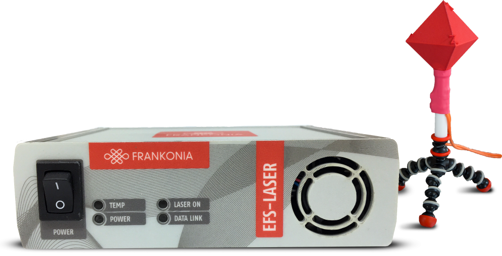
The Frankonia EFS-LASER Electric Field Probe especially has been designed for field strength measurements / field homogeneity measurements during radiated immunity tests according to IEC/EN 61000-4-3. However, it is also excellent to measure the radiation pollution of the environment, for example at workplaces or flats.
The EFS-LASER is an isotropic miniature E-field sensor to ensure, that the E-field will not be influenced by the size of the sensor itself. It even does not need any metering unit (which could also influence the field-strength), because of its direct fibre-optic output, which does allow direct connection of the sensor to the USB-interface of the control PC or laptop. The measuring values may be displayed via the individual IEC 61000-4-3 control software or via a windows-software included in the delivery.
The EFS-Laser cover the frequency-range from 10 KHz – 6 GHz. The utilized linearization technology provides a dynamic range up to 100 dB. The EFS-Laser is a smart, fast, extremely accurate electric field probe, which provides linearization, temperature compensation, control and communication functions. Noise reduction and temperature compensation allow accurate measurments down to 0.1 V/m. The probe is laser-powered to allow continuous, galvanically isolated operation without recharging or battery replacement The power supply unit comes in a small handy box.
Features
| Computer-Interface | |
| PC Interface | USB 2.0 |
| Application Software | included |
| Burst Trigger Output Level | 3.3 V CMOS |
| Burst Trigger Output Connector | BNC |
| Laser – Wavelength | 850 nm |
| Laser – Output Power | 750 mW |
| Laser – Shutdown Time | 1 ms |
| Fiber Optic Connector | FC / ST |
| Fiber Optic Cable Length | 15 m |
| Max. Fiber Optic Cable Length | 100 m (sold on request) |
| Input Voltage (power supply included) | 5V ± 5% |
| Input Current | < 2A |
| Ambient Temperature | 10 °C … 40 °C |
| Dimensions (W x D x H) | 483 x 43.5 (1HE) x 120mm |
| Field Sensor | |
| Frequency range | 10 kHz … 6GHz |
| Analog Rise Time 10 kHz … 100 MHz low Bandwidth 10 kHz … 100 MHz high Bandwidth 100 MHz … 6 GHz |
4 μs 40 ns 25 ns |
| Minimum Pulse Width Burst Mode Streaming Mode |
500 ns 2 μs |
| Resolution | < 0.01 dB |
| Sampling Rate Burst Mode Streaming Mode |
2 MSample/s > 500 kSample/s |
| Field Strength 10 kHz … 100 MHz 100 MHz … 6 GHz |
< 1 V/m … > 10 kV/m < 0.1 V/m … > 700 V/m |
| Damage Level 10 kHz … 100 MHz 100 MHz … 6 GHz |
40 kV/m 10 kV/m |
| Dynamic Range 10 kHz … 100 MHz 100 MHz … 6 GHz Isotropy, 900 MHZ |
80 dB … 100 dB 70 dB … 80 dB < 1dB |
| Amplitude Accuracy 10 kHz … 10 MHz (1.5 V/m to 30 V/m) > 10 MHz … 1 GHz (1 V/m to 80 V/m) > 1 GHz … 8 GHz (3 V/m to 100 V/m) |
1.3 dB 1.5 dB 1.0 dB |
| Linearity Error | < 0.1 dB |
| Temperature Stability | 0.1 dB |
| Ambient Temperature | 10 °C … 40°C |
| Dimensions (W x D x H) | 67 x 67 x 124 mm |
RF-Power Meter
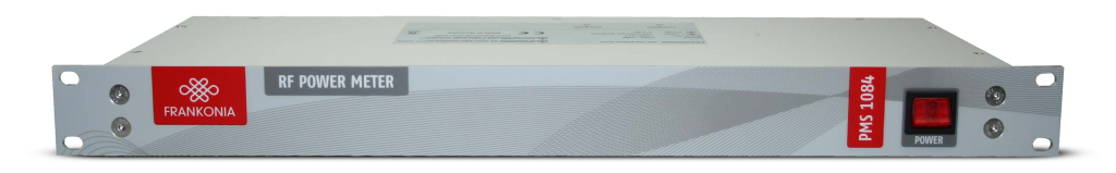
The PMS 1084 is in the standard version a 2-channel RF-Power Meter for the frequency range from 100 kHz up to 6 GHz or from 10 kHz to 500 MHz (PMS 1084 B). The measuring range reaches from –60 dBm to +20 dBm. It is possible to upgrade the PMS 1084 up to max. 4 measuring channels at any time. The measured values can be displayed via a software which is included in the delivery or via the control software of an automated test system. For the integration of the PMS 1084 into a remote-controlled test system it is equipped with serial and USB interface. Hence the PMS 1084 is very good suitable for the automated measurement of forward and reverse power in immunity test systems acc. to IEC/EN 61000-4-3 / -6. It is available for the installation into 19”-rack or as stand-alone unit.
| Technical specifications | PMS 1084 | PMS1084B |
| Number of channels | 2 (standard); up to 4 (option) | |
| Frequency range 2 x Input-Module LF | 10 kHz – 500 MHz | |
| Frequency range 2 x Input-Module HF | 100 kHz – 6 GHz | |
| Measuring range | -60 dBm to +20 dBm (10 kHz ≤ f ≤ 4 GHz) -45 dBm to +20 dBm (4 GHz < f ≤ 6 GHz) |
|
| Accuracy | ± 1 dB (0.5 dB typical) | |
| Resolution | 0.1 dB | |
| Integration time | 0.5 – 200 ms (firmware) | |
| Max. input level | +27 dBm (= 500mW) | |
| VSWR | up to 2GHz -> 1:1.15 2 – 4 GHz -> 1:1.25 4 – 6 GHz -> 1:1.35 |
|
| RF-Impedance | 50 Ω | |
| Interface (PC) | USB, RS232 (9-pol Sub D. female) | |
| Input | N-type female connector | |
| Dimensions (DxWxH) | 172 x 482.6 x 44.3 mm | |
| Weight | approx. 2.5 kg | |
| Power supply | 115/230 V | |
| Accessories included | Power cord, USB cable, application software, user manual | |
| Options | PMS 1084 | PMS1084B |
| PMS-CHA | Expansion of 1 measuring channel (max. up to 4 channels); 100 kHz to 6 GHz | |
| PMS-CHAB | Expansion of 1 measuring channel (max. up to 4 channels); 10 kHz to 500 MHz | |
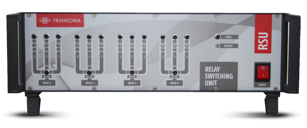
Relay-Switching-Unit
The RSU Relay Switching Unit is applicable for all fields of RF- and EMC measurements to switch (manualor remote-controlled) from one input to 2 or 3 outputs. Typical applications in measuring systemsare changeover switching between different amplifiers, antennas or power meters. This does also prevent circuit faults due to wrong cabling. By means of a selector switch on the front panel of the RSU it is possible to work in manual mode or remote- control mode via the RS232, USB or GPIB interface.
The input/output connectors of the relays are installed on the rear panel of the RSU, this allows an easy cabling when or where the RSU is mounted into a 19”-rack. A RSU can be equipped with a maximum of 4 relays with 2 or 3 outputs. The quantity of relays with 2 or respectively 3 outputs is variable. The delivery includes a Windows software for easy remote-controlled applications. However for extensive systems it is recommended to integrate the RSU driver into the system control software.
The easy to follow commands for RS232 and GPIB interfaces are listed in the user manual.
Definition of the relay assembly

| Technical specifications | RSU | |||
| Frequency range | DC to 12.4 GHz (up to 18 GHz or 40 GHz optional) | |||
| Test level | 50 V cont., 300 V (1s) at energetically used frequencies | |||
| DC…1GHz | 1 GHz…5 GHz | 5 GHz…10 GHz | 10 GHz…12.4 GHz | |
| VSWR | < 1.04 | < 1.14 | < 1.3 | < 1.5 |
| Isolation | > 90 dB | > 80 dB | > 70 dB | > 70 dB |
| Insertion loss | < 0.05 dB | < 0.1 dB | < 0.2 dB | < 0.3 dB |
| Max. power input | < 1.00 kW | < 0.44 kW | < 0.31 kW | < 0.28 kW |
| Impedance | 50 Ohm | |||
| Rf-connectors / Relays | N-Female | |||
| Switching time | < 60 ms | |||
| Number of operations | Max. 10/Minute | |||
| Operating temperature | +10°C… +40°C | |||
| Max. humidity | < 90% | |||
| Cabinet | 19″-subrack or desktop case | |||
| Dimensions (D x W x W) | 435.5×448.9×132.55mm | |||
| Weight | 7.6kg | |||
Antennas
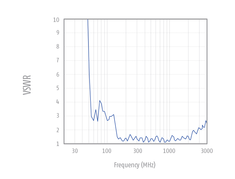
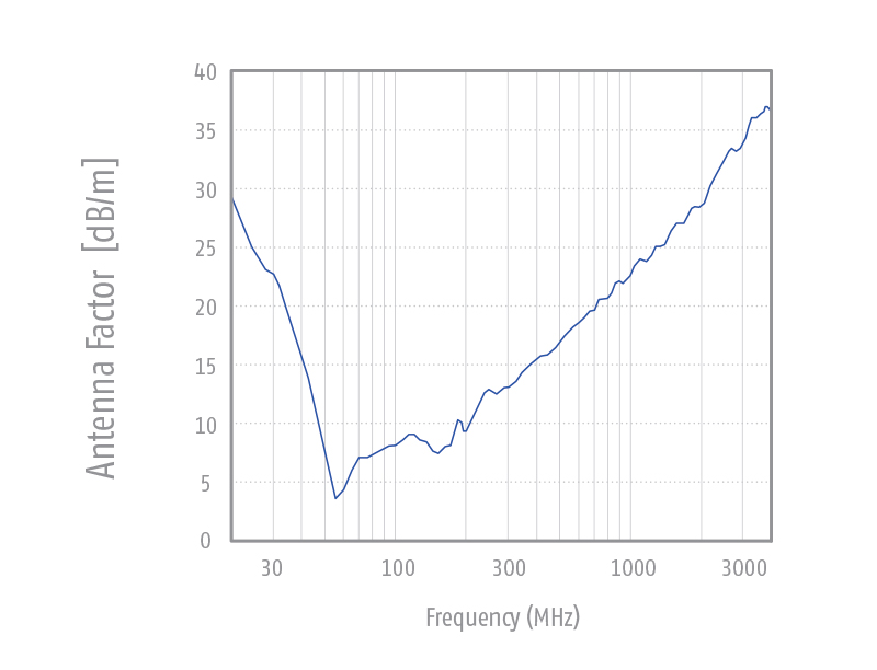
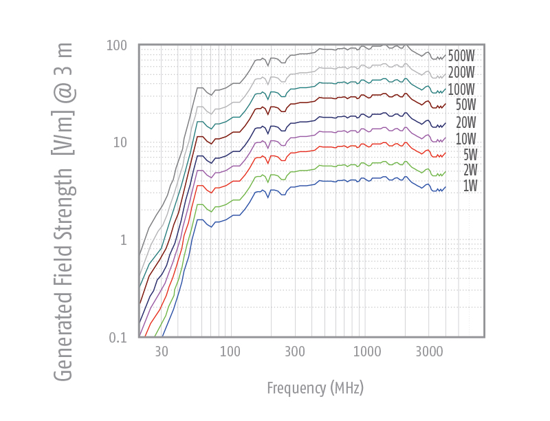
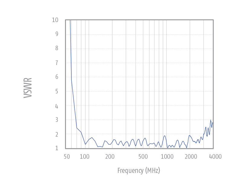
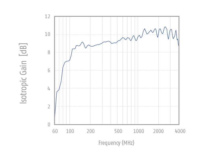
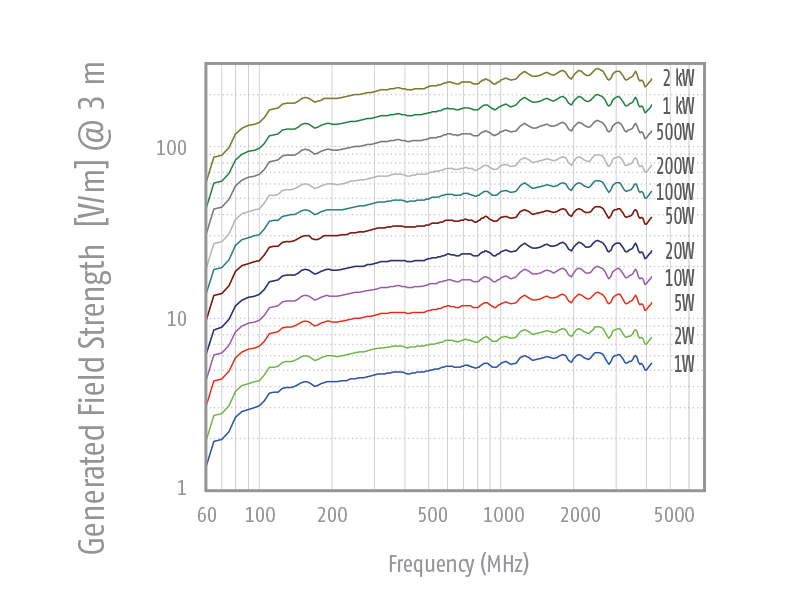
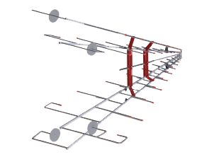
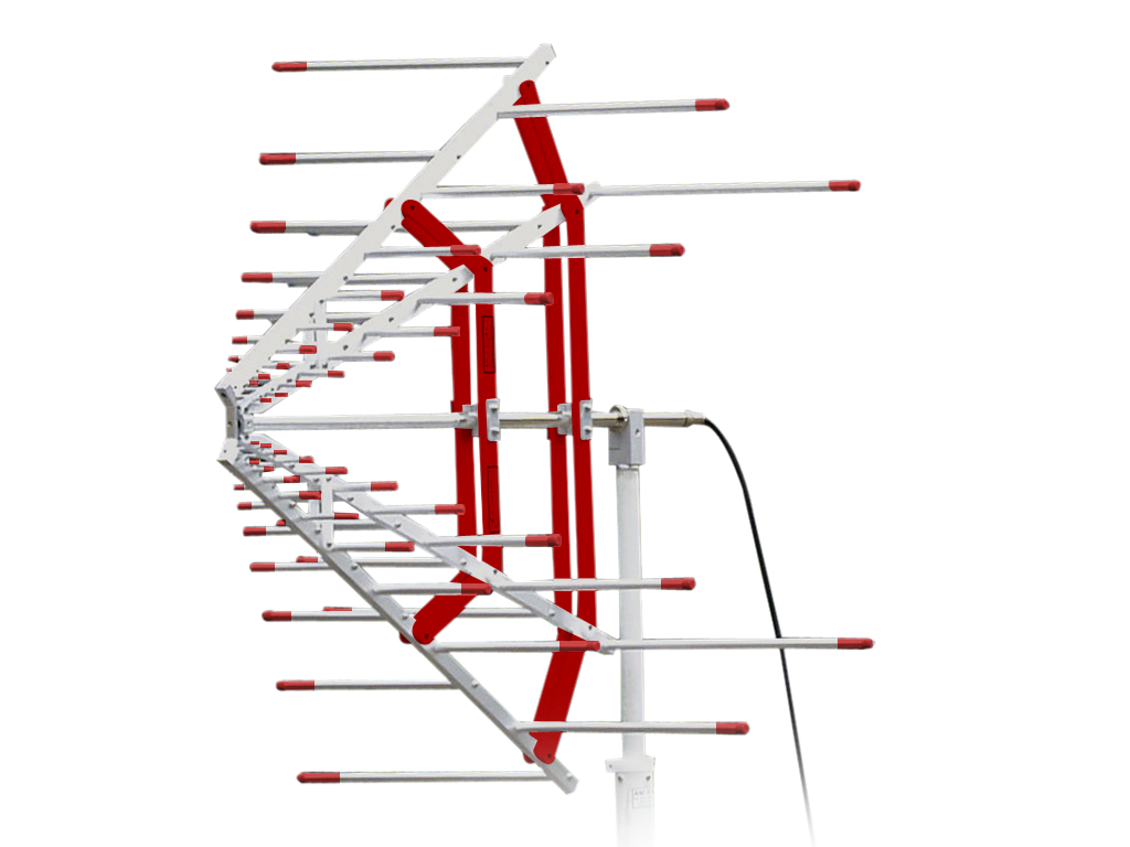
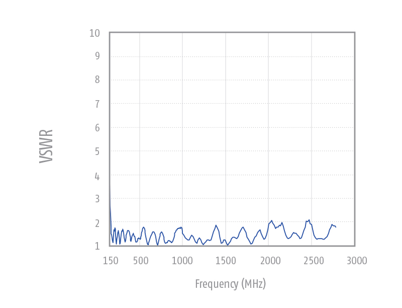
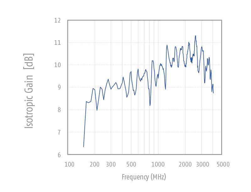
The ALX-4000 is an ultra-broadband antenna for emission measurements and immunity tests according to nearly all relevant international standards in the frequency range from 25 MHz up to 4 GHz. With regard to its mechanical structure it is a linear polarized logarithmic periodic broadband antenna for the higher frequency range, combined with a 4:1 broadband dipole (aluminum) for the low frequency range. This kind of ultra-broadband antenna allows performance of EMC test in one run, without time consuming antenna changes.

| Technical specifications | ALX-4000 |
| Frequency range | 25 MHz to 4 GHz |
| Max. input power | 100 MHz – 900 W 500 MHz – 300 W 1000 MHz – 210 W 2000 MHz – 140 W 3000 MHz – 100 W |
| Nominal impedance | 50 Ω |
| Connector | type N female |
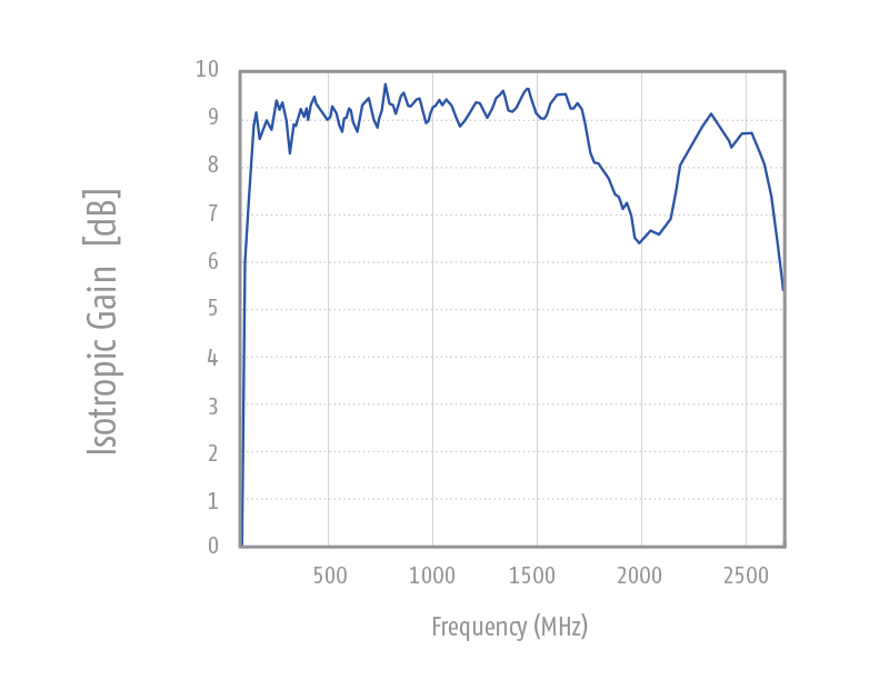
| Isotropic gain (LP-Section) | 6.4 +/- 1.2 dBi |
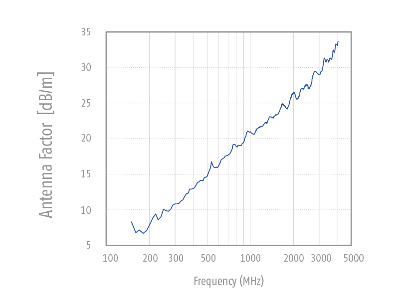
| Antenna factor | 4 … 37 dB/m |
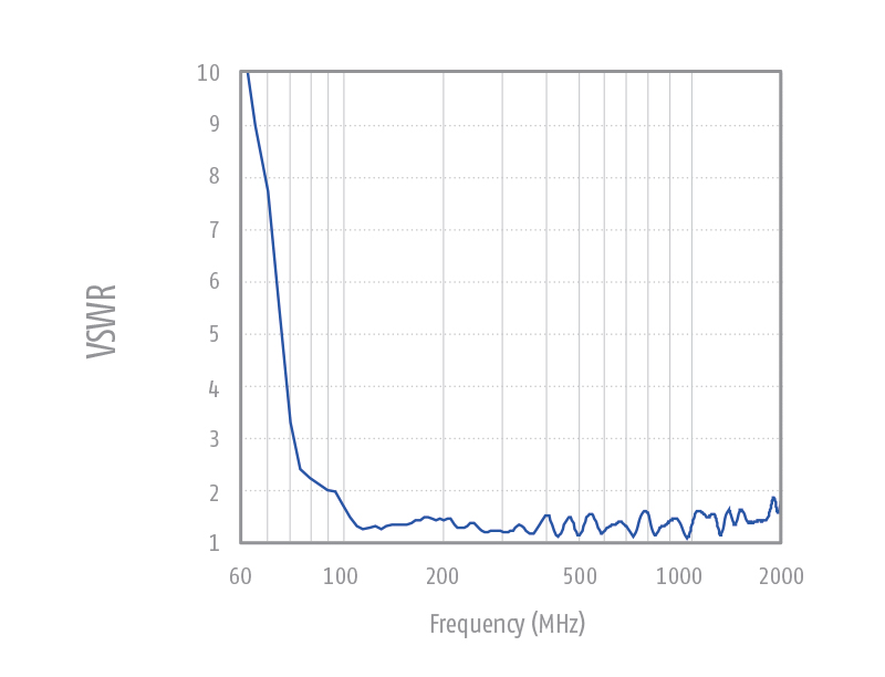
| Standing wave ratio SWR typ. | < 1.5 |
| Front to back ratio | 20 dB (f > 150 MHz) |
| Cross polarization | >20 dB (30 MHz…1 GHz) |
| 3 dB beamwidth typ. (E-Plane) | 45°-65° (f > 150 MHz) ≈ 78° (f < 150 MHz) |
| 3 dB beamwidth typ. (H-Plane) | 90°-120° (f > 150 MHz) |
| Dimensions (W x L x D) | 1500 x 910 (1240) x 620 mm |
| Weight | 3.1 kg |
| Fixation (indexing ring) | 22 mm tube |
| Use | Emission measurements Radiated immunity tests |

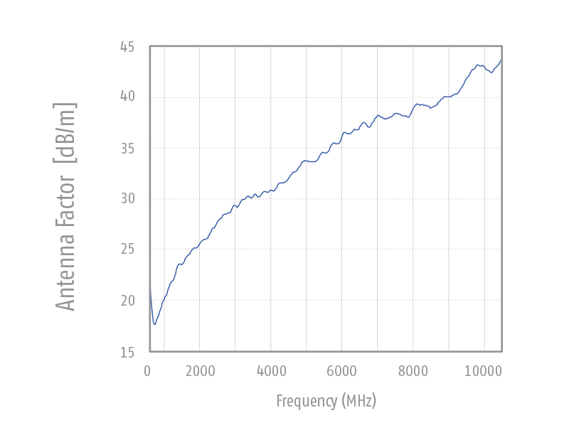
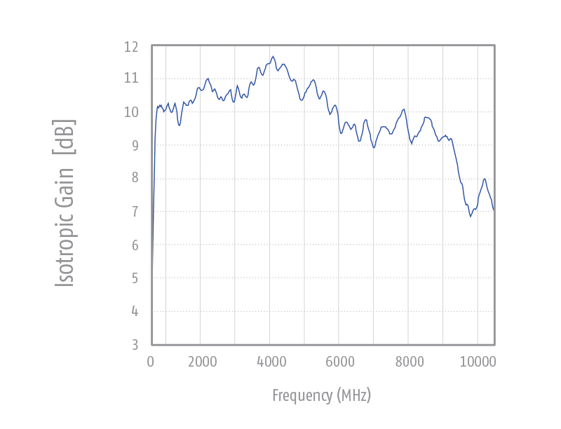
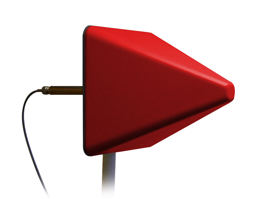
Stacked logarithmic-periodic broadband antenna for radiated immunity tests and emission measurements in the microwave frequency range. The antenna structure is made of laser-cut brass.
For protection of the fine antenna structure against damage the antenna is equipped with a low loss plastic protection cover. The MAX-9 is especially suitable for immunity testing acc. to IEC 61000-4-3 because of its good field uniformity. Further outstanding characteristics of the MAX-9 are the wide bandwidth, the nearly constant high gain, very good impedance matching as well as equal beamwidth in E- and H-plane.
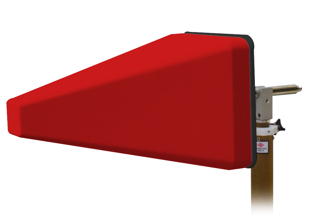
| Technical specifications | MAX-9 |
| Frequency range | 600 MHz – 10.5 GHz |
| Max input power | 300 W (f = 1 GHz) 150 W (f = 6 GHz) |
| Nominal impedance | 50 Ω |
| Connection | type N female |
| Isotropic Gain | typ. 10.3 dBi ± 1.5 dB |
| Antenna factor | 18 … 41 dB/m |
| SWR typical | < 1.5 (f < 7 GHz) |
| Front to back ratio | > 25 dB typ. |
| Cross polarization rejection | > 30 dB typ. |
| Half-power beamwidth (E-Plane) | 46° ± 10° |
| Half-power beamwidth (H-Plane) | 48° ± 10° |
| Dimensions (W x L x D) in mm | 460 (+215) x 270 x 270 |
| Weight | 3.7 kg |
| Fixation | Ø 22mm mounting tube |
| Use | Radiated immunity tests Emission measurements |
Technical specifications MAX-9-7/16
Same specifications as above with the following changes:
Frequency Range: 0.6 GHz – 7.5 GHz
Isotropic Gain: typ. 10.3 dBi,(0,6)0,7-7,5 GHz
Max. Input Power: 380 W (f = 5 GHz) | 950 W (f = 1 GHz)


Stacked logarithmic-periodic broadband antenna for radiated immunity tests and emission measurements in the microwave frequency range. The antenna structure is made of laser-cut brass.
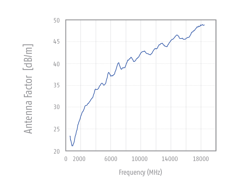
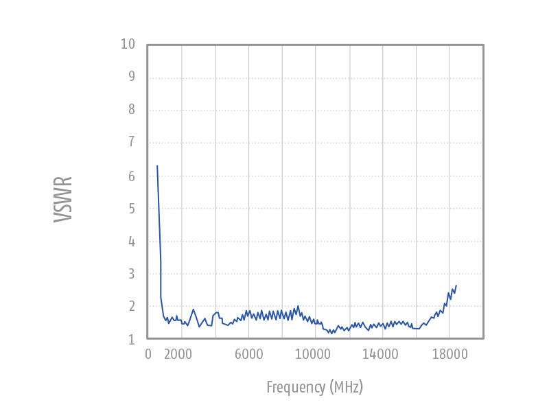
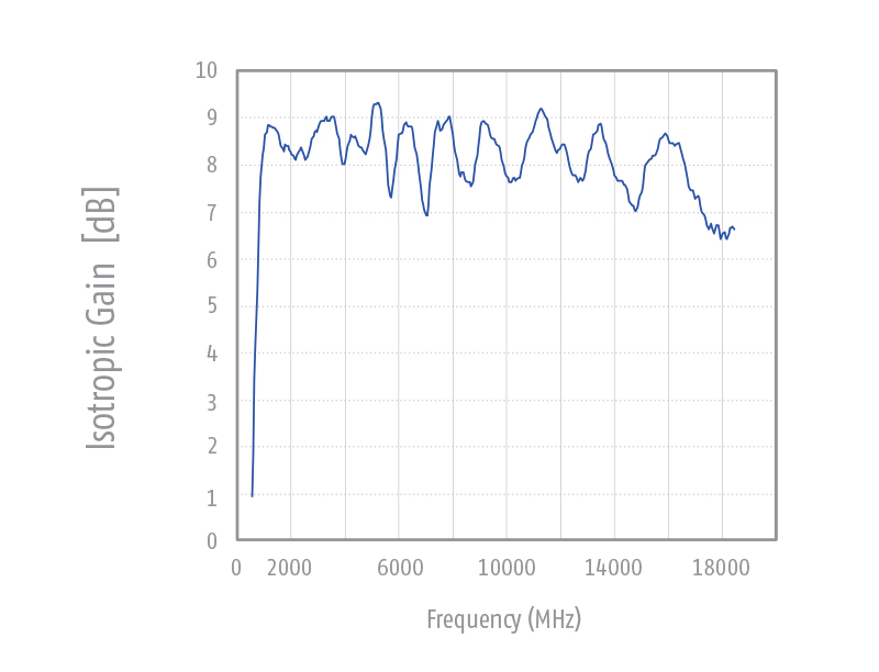
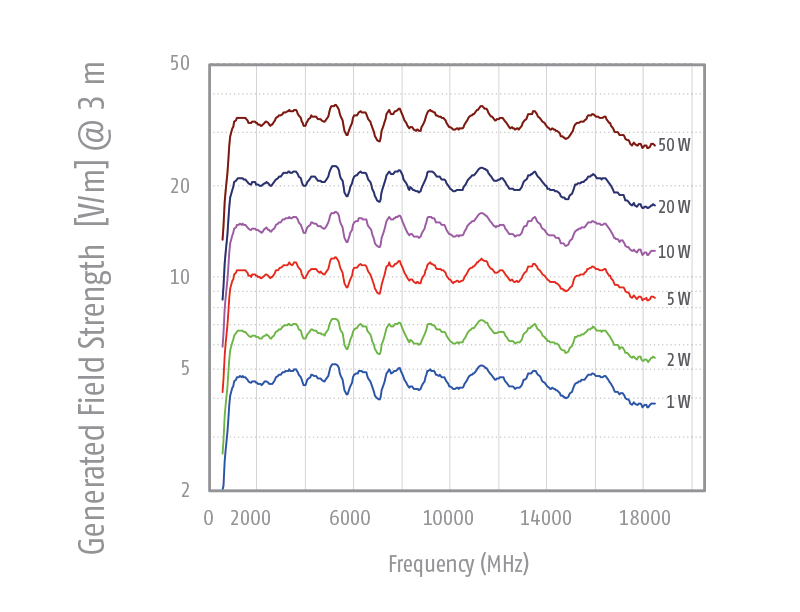
For protection of the fine antenna structure against damage the antenna is equipped with a low loss plastic protection cover. The MAX-18 is especially suitable for immunity testing acc. to IEC 61000-4-3 because of its good field uniformity. Further outstanding characteristics of the MAX-18 are the wide bandwidth, the nearly constant high gain, very good impedance matching as well as equal beamwidth in E- and H-Plane.
| Technical specifications | MAX-18 |
| Frequency range | 700 MHz – 20 GHz |
| Max input power | 50 W |
| Nominal impedance | 50 Ω |
| Connection | type N female |
| Isotropic Gain | typ. 8.6 dBi ± 1 dB |
| Antenna factor | 20 … 49 dB/m |
| SWR typical | < 2 |
| Dimensions (W x L x D) in mm | 490 x 270 x 270 |
| Weight | 1.2 kg |
| Front to back ratio | > 25 dB typ. |
| Cross polarization rejection | > 28 dB typ. |
| Half-power beamwidth (E-plane) | 58° |
| Half-power beamwidth (H-plane) | 60° |
The horn antennas HAX offer a very low SWR in their nominal frequency range and a very broad bandwidth. The gain increases with frequency up to approx. 18 dBi. The increasing gain with frequency helps to compensate cable losses.
The HAX series is suitable for both, transmission and receiving applications. The maximum allowed input power is only limited by the female N-connector. The detailed manual of the calibrated test antennas includes gain, antenna factor, SWR and directional patterns. The antenna is mounted with the 22 mm tube, equipped with a index ring for quick changes of polarization without using tools.

| Technical specifications | HAX-6 |
| Frequency range | 500 MHz – 6 GHz |
| Max input power | limited only by N-connector |
| Connection | type N female |
| Gain | 6 … 18 dBi |
| Antenna factor | 19 … 29 dB/m |
| Standing wave ratio SWR typ. | < 2 |
| Dimensions (W x L x D) in mm | 424 x 314 x 820 |
| Weight | 4.1 kg |
| Fixation | Ø 22mm mounting tube |
| Material | aluminium |
| Use | Radiated immunity tests Emission measurements |


Double-stacked log.-periodic antennas have mainly been developed in order to reach the highest field strength levels acc. to automotive-, avionics- and military standards with as less as possible input power. Antenna gain saves amplifier power!
The stacked design helps to focus the directional pattern of the H-plane somewhat, resulting in a typical gain improvement of 2.5dB compared to an ordinary LP antenna. This is especially important for immunity testing, where a maximum field strength and a good field uniformity is required. The beam- width in the E-plane and the H-plane are nearly identical, providing an optimized illumination of the EUT with minimized ground reflection influence.
Further the cross polar rejection of the AXL-80 is excellent and the high and flat gain of about 9dBi over a broad frequency range is the main advantage of the AXL-80. Because of its physical dimensions the main application of the AXL-80 is in bigger anechoic chambers / test sites for radiated immunity tests and emission measurements. From its technical / mechanical design it is a double- stacked log.-periodic antenna, consisting of two excellent ordinary log.-periodic structures. For easy transport and storage it is possible to remove the rear elements of the antenna, which are fixed by fast links.
| Technical specifications | AXL-80 |
| Frequency range | 70 MHz – 4 GHz |
| Max. input power | 1.5 kW (intermitt.) |
| (N-connector) | 1 kW (cont.) |
| Max. input power | 3 kW (intermitt.) |
| (7/16-connector) | 2 kW (cont.) |
| Nominal impedance | 50 Ω |
| Isotropic gain | 9 ± 2 dBi |
| Antenna factor | 2 … 32 dB/m |
| Standing wave ratio SWR typ. | 1.6 (f < 3GHz) |
| Front to back ratio | 8 – 22 dB |
| Cross polarization | > 30 dB |
| 3 dB beamwidth typ. (E-Plane) | 60° – 75° |
| 3 dB beamwidth typ. (H-Plane) | 50° – 65° |
| Dimensions (W x L x D) in mm | 1480 x 1480 x 1340 |
| Weight | 8.1 kg |
| Fixation | Ø 22mm mounting tube |
| Use | Emission measurements Radiated immunity tests |
The AXL-80ES special is nearly identical like the AXL-80E but with folded longest elements and smaller structure angle.
The stacked Log Periodic Dipole Antenna (Stacked LPDA) consists of two ordinary Log.-Per. structures. The excellent characteristics (flat gain over a large bandwidth, low SWR) of the ordinary LPDA designs could be maintained using the stacked LPDA design. The stacked design helps to focus the directional pattern of the H-plane somewhat, resulting in a typical gain improvement of 2.5 dB compared to an ordinary LP antenna. This is especially important for immunity testing, where a maximum field-strength and a good field uniformity is required. The beam width in the E-Plane and the H-plane are nearly identical, providing an optimized illumination of the EUT with minimized ground reflection influence. Further the cross polar rejection of the AXL-80ES is excellent. The fast-links allows to disassemble the rear elements without any need for further tools within a few seconds. These fast-links divide the antenna into five parts, which can be stored and transported easily.
| Technical specifications | AXL-80ES |
| Frequency range | 80 MHz – 2.7 GHz |
| Max. input power (N-connector) | 1 kW (const.) 1.5 kW (intermitt.) |
| Max. input power (7/16-connector) | 2 kW (cont.) 3 kW (intermitt.) |
| Nominal impedance | 50 Ω |
| Standing wave ratio SWR typ. | < 1.5 |
| 3 dB beamwidth typ. (E-Plane) | 47°-87° |
| 3 dB beamwidth typ. (H-Plane) | 41°-107° |
| Dimensions (W x L x D) in mm | 1500x1740x1400 |
| Weight | 9.8 kg |
| Fixation | Ø 22mm mounting tube |


The AXL-200 has especially been designed for the generation of high field strength levels acc. to automotive immunity standards. The small dimensions of the antenna does also allow to keep the min. required distance of 25cm to the floor, when testing in vertical polarization.
From the mechanical design it´s a double-stacked logarithmic periodic antenna, consisting of two excellent ordinary log.-periodic structures. This design guarantees a high and flat gain of 9-10dBi over a large bandwidth and a low SWR.
The stacked design helps to focus the directional pattern of the H-plane somewhat, resulting in a typical gain improvement of ca. 2 dB compared to an ordinary LP antenna. This is especially important for immunity testing, where a maximum field strength and a good field uniformity is required. The beamwidth in the E-plane and the H-plane are nearly identical, providing an optimized illumination of the EUT with minimized ground reflection influence. Further the AXL-200 has an excellent cross-polar rejection.
| Technical specifications | AXL-200 |
| Frequency range | 150 MHz – 4 GHz |
| Max. input power (N-connector) | 2 kW (intermitt.) 1 kW (cont.) |
| Max. input power (7/16-connector) | 3 kW (intermitt.) 2 kW (cont.) |
| Nominal impedance | 50 Ω |
| Isotropic gain | 9 … 10 ± 1 dBi |
| Antenna factor | 8 … 24 dB/m |
| Standing wave ratio SWR typ. | < 1.5 |
| Front to back ratio | > 16 dB |
| Cross polarization | >30 dB (200 MHz … 1 GHz) |
| 3 dB beamwidth typ. (E-Plane) | 64° – 53° |
| 3 dB beamwidth typ. (H-Plane) | 63° – 44° |
| Dimensions (W x L x D) | 930 x 890 x 940 |
| Weight | 4.6 kg |
| Fixation (indexing ring) | Ø 22mm mounting tube |
| Use | Radiated immunity tests and Emission measurements acc. to automotive standards |
MIL-STD 461, RS 101:
Test device:
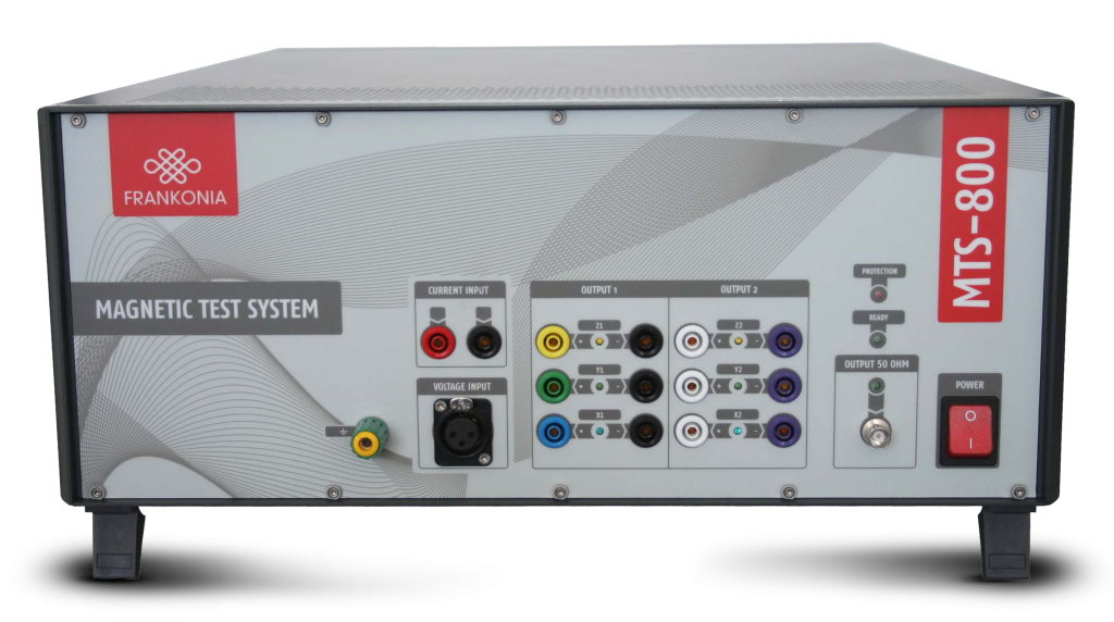
Magnetic-Field / Low-Frequency Test System
The MTS-800 is a compact test system for broadband generation and measurement of magnetic fields. Its internal components allow automatic EMC tests according to automotive standards where high field strength need to be generated or measured.
In combination with our triaxial Helmholtz coils full automated susceptibility tests are possible at magnetic field strength up to 1000 A/m for frequencies from DC to 1 kHz. Lower field strength can be generated for frequencies up to 250 kHz. Due to the triaxial setup of our Helmholtz coil major improvement in device handling is achieved because there is no need to turn an EUT during tests.
Tests and measurements are controlled by a program which will set most parameter automatically. For any relevant standard, which are fulfilled by the MTS-800, limit values are already included into the software package, although any different value can be defined by a user. After every test full reports will be created automatically. Report layout is pre-defined, though any user-defined layout is possible. High performance is guaranteed by a self-calibration.
Special Features
Options
Applications
Magnetic Field Generation
MTS-800 enables a user to generate strong magnetic fields up to 1000 A/m. Even alternating fields up to 250 kHz can be generated by the magnetic test system.
Low Frequency emission and immunity tests
acc. to MIL-STD 461, CE 101, RE 101, CS 101, CS 109 and RS 101. Individual software modules and hardware accessories are available for each of these tests.
Automotive Testing
Intensive testing is required for new products which should be used in any automotive application. The MTS-800 allows fast and easy testing according to many automotive standards as described before.
Technical specifications
| Voltage input (Analyzer) | |
| Frequency range | DC – 250 kHz |
| Input impedance | 1 MΩ / 50 Ω switchable |
| Connector | XLR, unbalanced |
| Max. input voltage | 100 V continuous (attenuator autoset at overvoltage); 10 V at 50 Ω |
| Gain | -20/0/20 dB Preamplifier, 0/20/40 bB ADC Amplifier; Self-calibration with ultra stable on-board reference |
| Current input | |
| Frequency range | DC – 250 kHz |
| Shunts | 10 mΩ / 1 Ω / 100 Ω |
| Max. input current | 20 A continuous (overload protection); 1 Ω and 100 Ω shunt are protected by an additional 1.5 A fuse |
| Connector | 4 mm safety jack (+, -) measurement via insulation amplifier or input jacks |
| Measurement range | 20 A, 10 A, 1 A, 100 mA, 10 mA, 1 mA automatic offset and gain; Self-calibration with ultra stable on-board reference |
| AD converter | |
| Resolution | 16 Bit |
| Sampling rate | 1.25 MSPS |
| Aliasingfilter | 0.01 dB Tschebyscheff filter, fg = 260 kHz; filter may be switched off |
| Generator | |
| Frequency range | DC – 250 kHz |
| Output impedance | 50 Ω |
| Connector | BNC, unbalanced |
| Signal | Sine wave / triangular / square wave / DC |
| Amplitude | 0 to 10 VAC, -10 V to +10 VDC |
| Resolution | 12 Bit (2.5 mV), Switchable – 20 dB Attenuator; Self-calibration with ultra stable on-board reference |
| Amplifier | |
| Frequency range | DC – 1 MHz |
| Connector | 4 mm safety jacks (output); BNC, unbalanced (input) |
| Current | 16 Arms |
| Voltage | 50 Vrms / 75 VDC |
| Distortion (DC-100 kHz, load ≥ 4 Ω) | < 0.10 % |
| General data | |
| EUT control / Connector | 9-pin Sub-D; RS232 |
| Connection to Computer | USB |
| Temperature range | 0 to 40 °C |
| Warm-up time | 15 min. |
| Housing | 19”-Subrack or desktop case |
| Dimensions (WxHxD) | 449 x 177 x 580 mm |
| Weight (shipping) | approx. 40 kg (net 34 kg) |
| Gain | 10 ±0.1% (±0.01% / °C) |
Features
Automatic Testing Capabilities
Full compliance with several immunity test as ISO 11452-8, MIL-STD-461 RS101, CS101, CS109, IEC/EN 55103-2, IEC/EN 61000-4-8, SAE J1113-2, SAE J1113-22, Ford ES-XW7T-1A278-AC, GM W3097, PSA B21 7110, Renault 36-00-808, DC-11224, DC 10614 and similar standards. Furthermore the MTS-800 allows emission measurements according to MILSTD- 461E/F RE101, CE101 and IEC/EN 55103-1.
Software
Any function is controlled via a software which also guide the user through any test or measurement. Adaptation of signal strength or measurement graphs are possible at any stage. User defined signals complement the usage for fast and reliable tests. The software is written in LabVIEW which guarantees stable and fast performance on any Microsoft® Windows platform.
Components
MTS-800 consists of 3 independent modules: a signal generator (DC – 250 kHz), a power amplifier (800 W output maximum, DC –1MHz bandwidth) and spectrum analyzer (16 Bit, 1 MSPS sampling rate). All modules can be used as stand-alone units.
Self-calibration
Using an ultra-stable voltage source self-calibration correction values are stored in an internal EEPROM. Any voltage signal or voltage measurement device is calibrated at a self-calibration process automatically in about a minute.
Accessories
Frankonia provides also many different coils and loop sensor which are ideally suited for the described tests. Any additional equipment is ready to use without a need for recalibration. Not only our own equipment can be used with the MTS-800, but also user defined coils. A calibration mode is included in the software to complement the magnetic test system with any further equipment.
Further features and possibilities
Helmholtz Coils
Several Helmholtz coils are available for susceptibility tests. We also offer tri-axial Helmholtz coils which are suitable for MTS-800. To achieve 1000 A/m at 1 kHz, it is absolute necessary to use our Helmholtz coils and an optional compensation board.
| Coil Type | Technical specifications |
| HCST_50/28_TAP (1) | Tapped triaxial Helmholtz coil for immunity tests |
| HCS_50/28_TAP (2) | Tapped single axis Helmholtz coil for immunity tests |
| Max. current | Designed for the generation of magnetic fields with field strength > 1000 A/m |
| HCS_125/75_TAP | Tapped single axis Helmholtz coil for immunity tests according to IEC / EN 55103 |
Loop Sensors / Radiating Loops
For immunity tests we offer radiating loops which are necessary to generate magnetic fields. The required loop sensors for measuring emission can also be ordered.
| Coil Type | Technical specifications |
| RL_120 (3) | 120 mm radiating loop according to MIL-STD-461 |
| LS_040 (4) | Electrostatically shielded loop sensor according to MIL-STD-461 |
| LS_133 | Electrostatically shielded loop sensor according to MIL-STD-461 |
| RS_133 | Electrostatically shielded loop sensor according to IEC/EN 55103-1/2 |
| Can be used as radiating loop and loop sensor. | |
Coupling Transformer
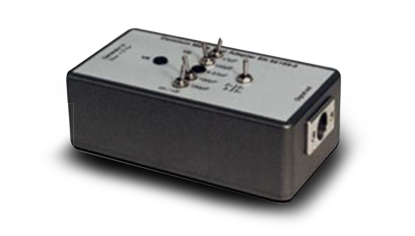
MIL-STD-461 CS 101 requires a coupling transformer for conducted susceptibility tests. Frankonia has developed a coupling transformer which meets all requirements. Due to direct coupling to voltage mains, the coupling transormer has an additional differential amplifier for common mode rejection of the AC mains. Using the coupling transformer without this amplifier can destroy any measurement instrument due to overvoltage.
Testing equipment acc. to IEC/EN 55103-2
IEN/EN 55103-2 requires certain immunity tests for frequencies from 50 Hz to 10 KHz. The following test equipment fulfills all requirements according to IEC/EN 55103-2, annex B.
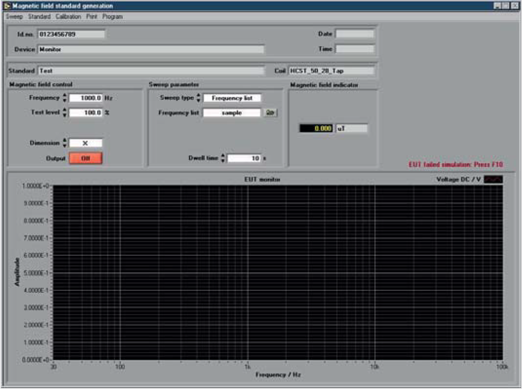
Control Panel
The software starts with the generator/amplifier control panel. This window allows basic settings of generator and amplifier.
Standard generation window
Open the Magnetic field generation window for susceptibility tests according to predefined standards.
Magnetic field continuous generation window
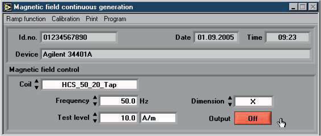
Open the continuous generation window for long term magnetic field test.
Example standard file
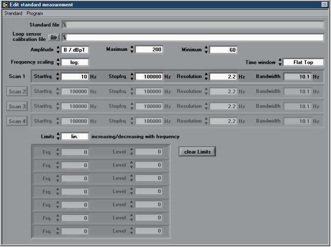
Edit a predefined standard or create a new one. Load, save and print data.
Measurement results
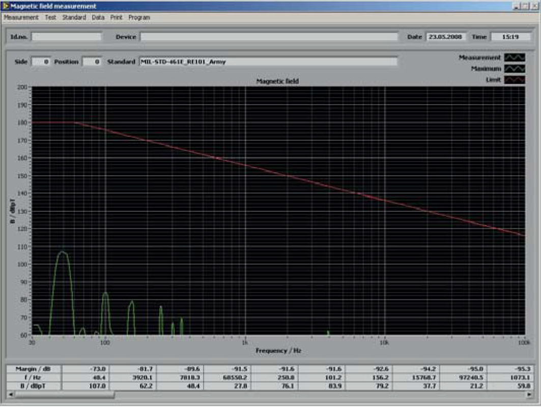
Open the Magnetic field measurement window for spectrum analyzer measurements. Perform a single or continuous measurement. Perform test according to predefined standards.
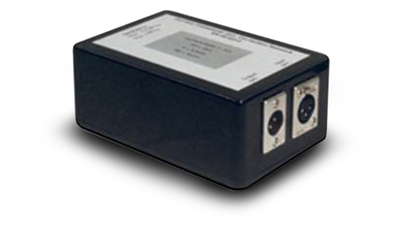
Current transducer incl. correction network
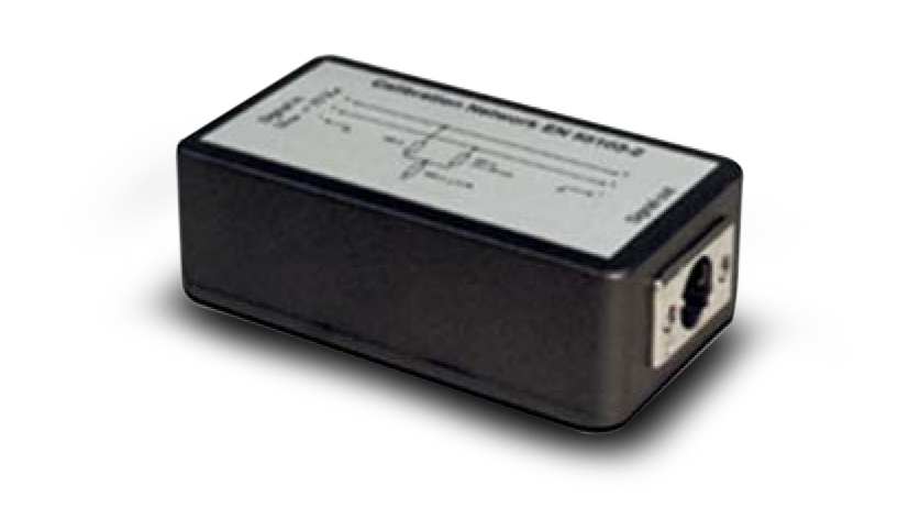
Calibration network
Common mode test adapter
Accessories selecting table
| Test equipment MIL-STD 461 | Recommended Model | CE101 | CS101 | CS109 | RE101 | RS101 |
| Measurement receiver | MTS-800 | • | • | • | • | |
| Current probe | Any commercially available model | • | • | • | ||
| Signal generator | MTS-800 | • | • | • | • | • |
| Power amplifier | MTS-800 | • | • | • | ||
| Data recording device | MTS-800 | • | • | |||
| Oscilloscope | MTS-800 | • | • | |||
| Coupling transformer | CT_2.5/50 AC | • • | ||||
| Isolation transformer | IT-6/-16/-20/ | • | • | |||
| LISNs | Any commercially available model | • • • • | ||||
| Radiating loop 12cm | RL_120 | • | ||||
| Loop sensor 4cm | LS_040 | • | ||||
| Loop sensor 13.3cm | LS_133 | • | ||||
| Ohmmeter | Any commercially available model | • | ||||
Standards
| CE101 | Conducted Emission, Power Leads, 30 Hz to 10 kHz |
| CS101 | Conducted Susceptibility, Power Lead, 30 Hz to 150 kHz |
| CS109 | Conducted Susceptibility, Structure Current, 60 Hz to 100 kHz |
| RE101 | Radiated Emission, Magnetic Field, 30 Hz to 100 kHz |
| RS101 | Radiated Susceptibility, Magnetic Field, 30 Hz to 100 kHz |