Radiated Immunity
[us_page_title description=”1″ font_size=”1.8rem” inline=”1″]
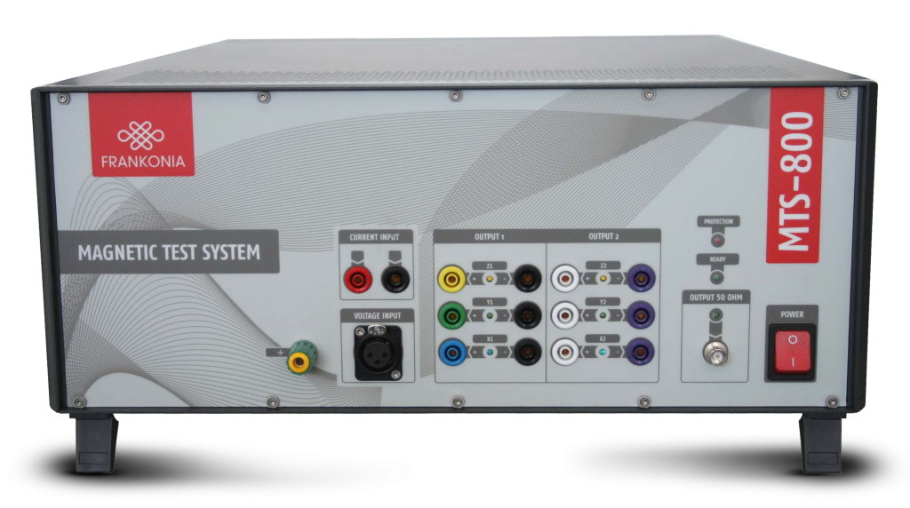
Magnetic-Field / Low-Frequency Test System
The MTS-800 is a compact test system for broadband generation and measurement of magnetic fields. Its internal components allow automatic EMC tests according to automotive standards where high field strength need to be generated or measured.
In combination with our triaxial Helmholtz coils full automated susceptibility tests are possible at magnetic field strength up to 1000 A/m for frequencies from DC to 1 kHz. Lower field strength can be generated for frequencies up to 250 kHz. Due to the triaxial setup of our Helmholtz coil major improvement in device handling is achieved because there is no need to turn an EUT during tests.
Tests and measurements are controlled by a program which will set most parameter automatically. For any relevant standard, which are fulfilled by the MTS-800, limit values are already included into the software package, although any different value can be defined by a user. After every test full reports will be created automatically. Report layout is pre-defined, though any user-defined layout is possible. High performance is guaranteed by a self-calibration.
Special Features
Options
Applications
Magnetic Field Generation
MTS-800 enables a user to generate strong magnetic fields up to 1000 A/m. Even alternating fields up to 250 kHz can be generated by the magnetic test system.
Low Frequency emission and immunity tests
acc. to MIL-STD 461, CE 101, RE 101, CS 101, CS 109 and RS 101. Individual software modules and hardware accessories are available for each of these tests.
Automotive Testing
Intensive testing is required for new products which should be used in any automotive application. The MTS-800 allows fast and easy testing according to many automotive standards as described before.
Technical specifications
| Voltage input (Analyzer) | |
| Frequency range | DC – 250 kHz |
| Input impedance | 1 MΩ / 50 Ω switchable |
| Connector | XLR, unbalanced |
| Max. input voltage | 100 V continuous (attenuator autoset at overvoltage); 10 V at 50 Ω |
| Gain | -20/0/20 dB Preamplifier, 0/20/40 bB ADC Amplifier; Self-calibration with ultra stable on-board reference |
| Current input | |
| Frequency range | DC – 250 kHz |
| Shunts | 10 mΩ / 1 Ω / 100 Ω |
| Max. input current | 20 A continuous (overload protection); 1 Ω and 100 Ω shunt are protected by an additional 1.5 A fuse |
| Connector | 4 mm safety jack (+, -) measurement via insulation amplifier or input jacks |
| Measurement range | 20 A, 10 A, 1 A, 100 mA, 10 mA, 1 mA automatic offset and gain; Self-calibration with ultra stable on-board reference |
| AD converter | |
| Resolution | 16 Bit |
| Sampling rate | 1.25 MSPS |
| Aliasingfilter | 0.01 dB Tschebyscheff filter, fg = 260 kHz; filter may be switched off |
| Generator | |
| Frequency range | DC – 250 kHz |
| Output impedance | 50 Ω |
| Connector | BNC, unbalanced |
| Signal | Sine wave / triangular / square wave / DC |
| Amplitude | 0 to 10 VAC, -10 V to +10 VDC |
| Resolution | 12 Bit (2.5 mV), Switchable – 20 dB Attenuator; Self-calibration with ultra stable on-board reference |
| Amplifier | |
| Frequency range | DC – 1 MHz |
| Connector | 4 mm safety jacks (output); BNC, unbalanced (input) |
| Current | 16 Arms |
| Voltage | 50 Vrms / 75 VDC |
| Distortion (DC-100 kHz, load ≥ 4 Ω) | < 0.10 % |
| General data | |
| EUT control / Connector | 9-pin Sub-D; RS232 |
| Connection to Computer | USB |
| Temperature range | 0 to 40 °C |
| Warm-up time | 15 min. |
| Housing | 19”-Subrack or desktop case |
| Dimensions (WxHxD) | 449 x 177 x 580 mm |
| Weight (shipping) | approx. 40 kg (net 34 kg) |
| Gain | 10 ±0.1% (±0.01% / °C) |
Features
Automatic Testing Capabilities
Full compliance with several immunity test as ISO 11452-8, MIL-STD-461 RS101, CS101, CS109, IEC/EN 55103-2, IEC/EN 61000-4-8, SAE J1113-2, SAE J1113-22, Ford ES-XW7T-1A278-AC, GM W3097, PSA B21 7110, Renault 36-00-808, DC-11224, DC 10614 and similar standards. Furthermore the MTS-800 allows emission measurements according to MILSTD- 461E/F RE101, CE101 and IEC/EN 55103-1.
Software
Any function is controlled via a software which also guide the user through any test or measurement. Adaptation of signal strength or measurement graphs are possible at any stage. User defined signals complement the usage for fast and reliable tests. The software is written in LabVIEW which guarantees stable and fast performance on any Microsoft® Windows platform.
Components
MTS-800 consists of 3 independent modules: a signal generator (DC – 250 kHz), a power amplifier (800 W output maximum, DC –1MHz bandwidth) and spectrum analyzer (16 Bit, 1 MSPS sampling rate). All modules can be used as stand-alone units.
Self-calibration
Using an ultra-stable voltage source self-calibration correction values are stored in an internal EEPROM. Any voltage signal or voltage measurement device is calibrated at a self-calibration process automatically in about a minute.
Accessories
Frankonia provides also many different coils and loop sensor which are ideally suited for the described tests. Any additional equipment is ready to use without a need for recalibration. Not only our own equipment can be used with the MTS-800, but also user defined coils. A calibration mode is included in the software to complement the magnetic test system with any further equipment.
Further features and possibilities
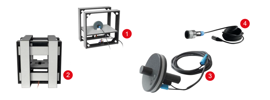
Helmholtz Coils
Several Helmholtz coils are available for susceptibility tests. We also offer tri-axial Helmholtz coils which are suitable for MTS-800. To achieve 1000 A/m at 1 kHz, it is absolute necessary to use our Helmholtz coils and an optional compensation board.
| Coil Type | Technical specifications |
| HCST_50/28_TAP (1) | Tapped triaxial Helmholtz coil for immunity tests |
| HCS_50/28_TAP (2) | Tapped single axis Helmholtz coil for immunity tests |
| Max. current | Designed for the generation of magnetic fields with field strength > 1000 A/m |
| HCS_125/75_TAP | Tapped single axis Helmholtz coil for immunity tests according to IEC / EN 55103 |
Loop Sensors / Radiating Loops
For immunity tests we offer radiating loops which are necessary to generate magnetic fields. The required loop sensors for measuring emission can also be ordered.
| Coil Type | Technical specifications |
| RL_120 (3) | 120 mm radiating loop according to MIL-STD-461 |
| LS_040 (4) | Electrostatically shielded loop sensor according to MIL-STD-461 |
| LS_133 | Electrostatically shielded loop sensor according to MIL-STD-461 |
| RS_133 | Electrostatically shielded loop sensor according to IEC/EN 55103-1/2 |
| Can be used as radiating loop and loop sensor. | |
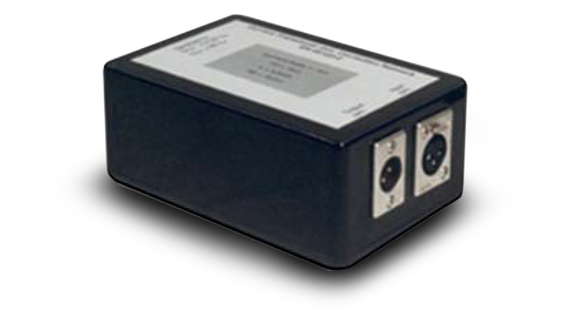
Coupling Transformer
MIL-STD-461 CS 101 requires a coupling transformer for conducted susceptibility tests. Frankonia has developed a coupling transformer which meets all requirements. Due to direct coupling to voltage mains, the coupling transormer has an additional differential amplifier for common mode rejection of the AC mains. Using the coupling transformer without this amplifier can destroy any measurement instrument due to overvoltage.
Testing equipment acc. to IEC/EN 55103-2
IEN/EN 55103-2 requires certain immunity tests for frequencies from 50 Hz to 10 KHz. The following test equipment fulfills all requirements according to IEC/EN 55103-2, annex B.
Control Panel
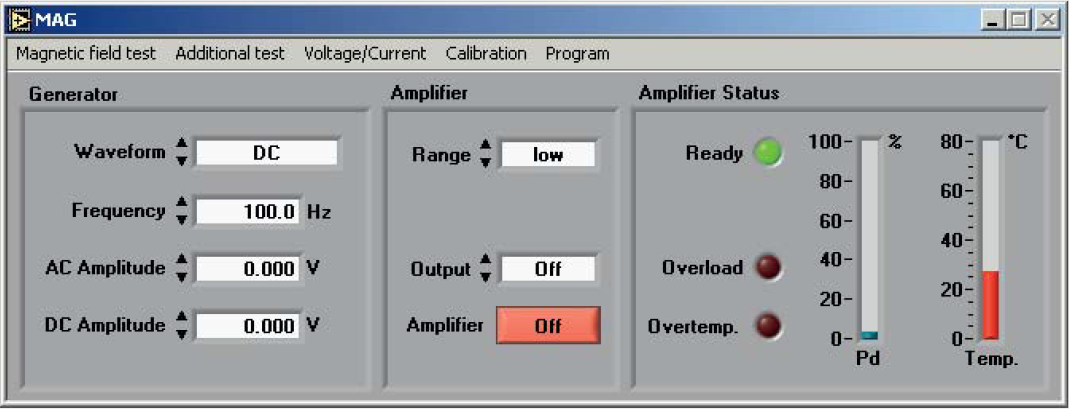
The software starts with the generator/amplifier control panel. This window allows basic settings of generator and amplifier.
Standard generation window
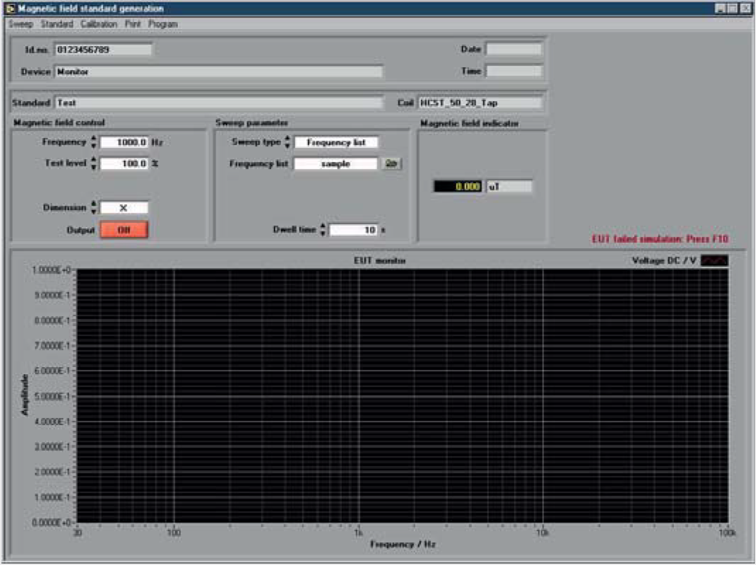
Open the Magnetic field generation window for susceptibility tests according to predefined standards.
Magnetic field continuous generation window
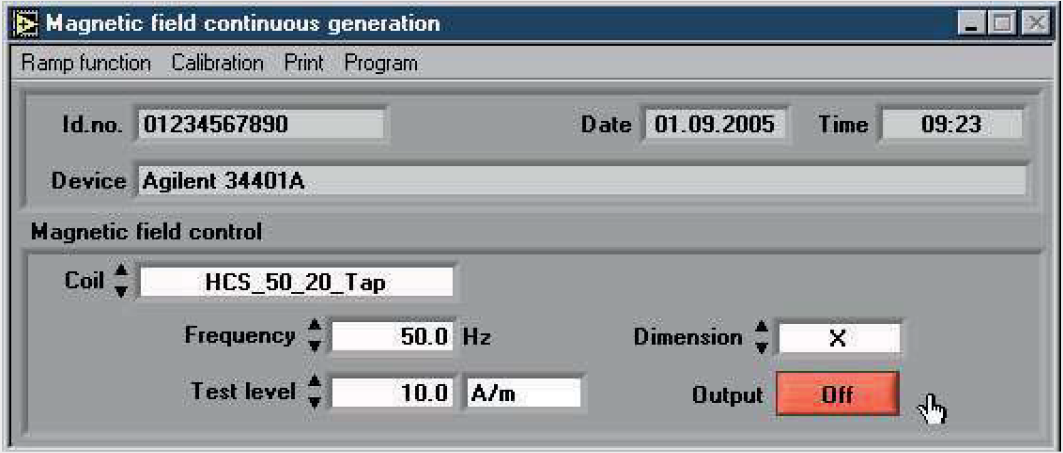
Open the continuous generation window for long term magnetic field test.
Example standard file
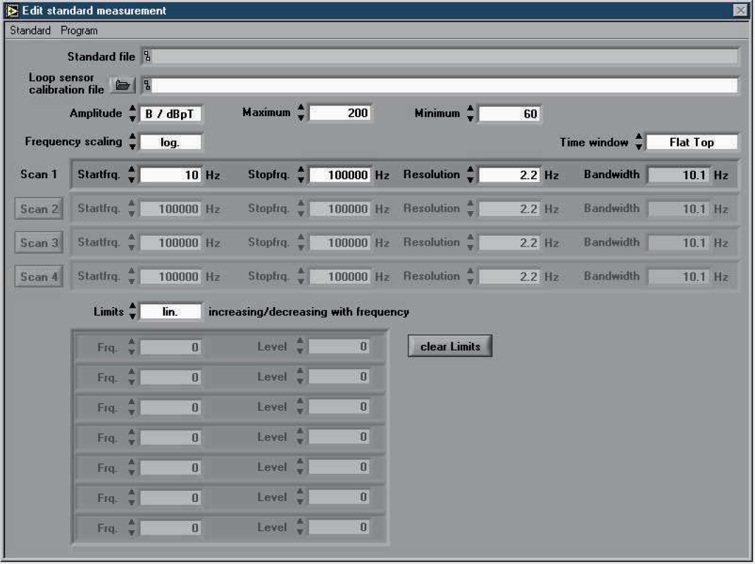
Edit a predefined standard or create a new one. Load, save and print data.
Measurement results
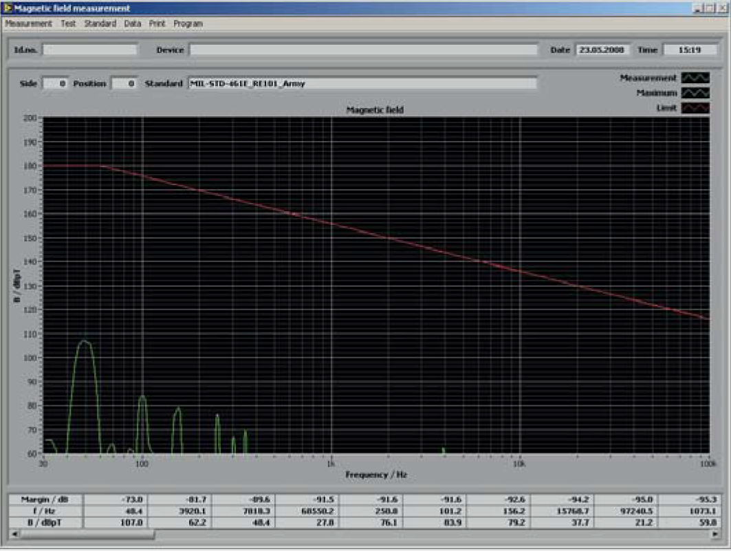
Open the Magnetic field measurement window for spectrum analyzer measurements. Perform a single or continuous measurement. Perform test according to predefined standards.
Current transducer incl. correction network
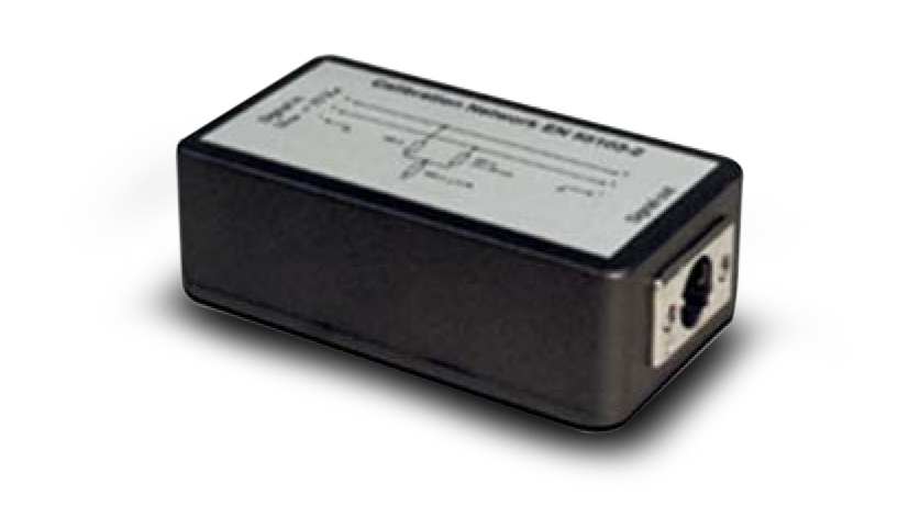
Calibration network
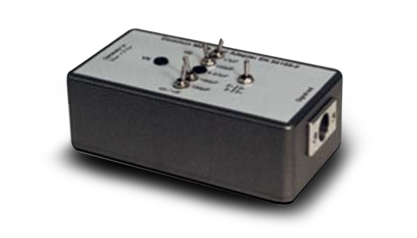
Common mode test adapter
Accessories selecting table
| Test equipment MIL-STD 461 | Recommended Model | CE101 | CS101 | CS109 | RE101 | RS101 |
| Measurement receiver | MTS-800 | • | • | • | • | |
| Current probe | Any commercially available model | • | • | • | ||
| Signal generator | MTS-800 | • | • | • | • | • |
| Power amplifier | MTS-800 | • | • | • | ||
| Data recording device | MTS-800 | • | • | |||
| Oscilloscope | MTS-800 | • | • | |||
| Coupling transformer | CT_2.5/50 AC | • • | ||||
| Isolation transformer | IT-6/-16/-20/-20/3P | • | • | |||
| LISNs | Any commercially available model | • • • • | ||||
| Radiating loop 12cm | RL_120 | • | ||||
| Loop sensor 4cm | LS_040 | • | ||||
| Loop sensor 13.3cm | LS_133 | • | ||||
| Ohmmeter | Any commercially available model | • | ||||
Standards
| CE101 | Conducted Emission, Power Leads, 30 Hz to 10 kHz |
| CS101 | Conducted Susceptibility, Power Lead, 30 Hz to 150 kHz |
| CS109 | Conducted Susceptibility, Structure Current, 60 Hz to 100 kHz |
| RE101 | Radiated Emission, Magnetic Field, 30 Hz to 100 kHz |
| RS101 | Radiated Susceptibility, Magnetic Field, 30 Hz to 100 kHz |