Conducted Immunity
[us_page_title inline=”1″ description=”1″ font_size=”1.8rem”]
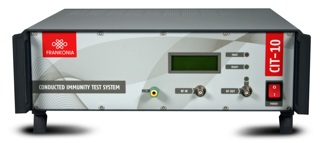
CIT-10
The CIT-10 is a complete test system for conducted RF-immunity tests according to IEC/EN 61000-4-6, ISO 11452-4, MIL-STD 461 CS114, SAE-J1113-2, DC 10614 and similar standards. Its internal RFgenerator and RF-power amplifier produce output signals with max. up to 150 W within a frequency range from 100 (10) kHz up to 400 MHz. Generated signals are measured via one of the max. 3 internal RFVolt-meters. Furthermore via an optional, internal directional coupler forward and reflected power can be measured. The whole test system allows full au-tomatic tests for the specified frequency range. As a “stand-alone” test system the CIT-10 is convincing by its easy and comfortable handling and the excellent cost-performance ratio. Addons like coupling/decou-pling devices are available as well.
Special Features
Applications
Immunity Testing
Testing according to IEC/EN 61000-4-6, ISO 11452-4, MIL-STD 461 CS114, DC10614 can be performed automatically.
Generation, amplification and
verification of RF-Signals
The internal amplifier amplifies any signal from 100 (10) kHz up to 400 MHz. By using the internal generator a desired narrowband signal can be generated. Signals up to 30 dBm can be measured at the same time. If a directional coupler is installed, forward and reflected power are measured as well.
Technical specifications
| RF Voltmeter (external in-/output) |
CIT-10 |
| Frequency range | 10 kHz to 400 MHz |
| Measuring range | +30 dBm to -40 dBm |
| Accuracy | ±0.5 dB |
| VSWR | < 1.1 : 1 |
| Input | BNC, 50 Ω |
| RF-Signal Generator | CIT-10 |
| Output | BNC, 50 Ω |
| Frequency range | 10 kHz to 400 MHz |
| Frequency resolution | 1 Hz |
| Output level range | 0 to – 63 dBm |
| Output level resolution | 0.1 dB |
| Ouput level accuracy | ±0.5 dB (± 1 dB max) |
| Accuracy (frequency) | ±5 ppm (TCXO) |
| Harmonics | < -30 dBc |
| Non harmonics | < -45 dBc |
| Amplitude modulation (internal) | 0 to 100 %; resolution 0.5 % (internal AF-Generator) |
| Amplitude modulation (external) | BNC jack 1 Hz to 100 kHz, 0 to 100% Input impedance > 100 kΩ |
| Pulse modulation | variable duty cycle 10 – 90 %; resolution 1 % (internal AF Generator) |
| VSWR | < 1.5:1 |
| RF Generator | CIT-10 |
| Output jack | BNC |
| Frequency range | 1 Hz to 100 kHz |
| Frequency resolution | 0.1 Hz |
| Output voltage | 0 to 1 V amplitude; resolution 5 mV |
| Accuracy (frequency) | ±50 ppm |
| Signal | Sine wave / square wave / triangular |
| RF-Voltmeter (internal, 2 pcs.) | CIT-10 |
| Frequency range | 10 kHz to 400 MHz |
| Measuring range | +53 dBm to – 0 dBm |
| Accuracy | ±0.5 dB |
| Directional coupler (optional) | CIT-10 |
| Frequency range | 10 kHz to 400 MHz |
| Power | 200 W CW |
| Insertion loss | 0.5 dB max |
| VSWR | 1.25 : 1 max |
| Directivity | 20 dB min |
Technical specifications
| RF-Power Amplifier | CIT-10 | ||
| Frequency Range | Power | Gain | Distortion |
| 10kHz – 250 MHz | 75 W | 51 dB ± 1.5 dB | < -20dBC @ 50W |
| 100kHz – 400 MHz | 75 W | 51 dB ± 1.5 dB | < -20dBC @ 50W |
| 100kHz – 250 MHz | 75 W | 46 dB ± 1.5 dB | < -20dBC @ 20W |
| Input impedance | 50 Ω, VSWR < 1.5:1 | ||
| Output impedance | 50 Ω, VSWR < 1.5:1 | ||
| EUT-fail input | CIT-10 |
| Input resistance | 2.2 kΩ |
| Level | TTL/CMOS compatible, optical decoupled |
| EUT-Monitor input | CIT-10 |
| Input voltage | 0-10 V |
| Input impedance | 100 kΩ |
| Amplifier monitor | CIT-10 |
| Output | BNC, 50 Ω |
| Level | -40 dB (amplifier output), ±3 dB |
| Interface | CIT-10 |
| USB-A | Multimeter (for EUT control) |
| USB-A | Relay switching unit |
| USB-B | Connection to computer |
| General data | CIT-10 |
| Temperature range | 0 to 40 °C |
| Warm-up time | 15 min. |
| Housing | 19”-Subrack or desktop case |
| Dimension (W x H x D) | 449 mm x 133 mm x 435.5 mm |
| AC input | 100 – 240 VAC; 50/60 Hz |
| Volume of delivery | CIT-10 (basic equipment), cabling, system software |
| Part Number | CIT-10/25 with integrated 25 W RF-power amplifier |
| Part Number | CIT-10/75 with integrated 75 W RF-power amplifier |
| Part Number | CIT-10/75MIL with integrated 75 W RF-power amplifier |
| Part Number | CIT-10/W without internal RF-power amplifier |
Features
Internal RF-Power Amplifier
Several amplifier modules are available. Highest output power can be 75 W over the specified frequency range. The amplifier input can be accessed via the back panel of the CIT-10, so that the amplifier can also be used with any external generator. 25 W and 75 W amplifiers are available as standard.
Amplitude Modulation
Frequencies generated by the generator can also be modulated with a LF signal. Modulation frequencies may vary from 1 Hz up to 100 kHz, modulation levels are available from 0 % to 100 %.
BCI-Tests with additional RF-Power Meter
Frequencies generated by the generator can also be modulated with a LF signal. Modulation frequencies may vary from 1 Hz up to 100 kHz, modulation levels are available from 0 % to 100 %.
Internal RF-Voltmeter
Accurate measurements of RF signals from -40 dBm up to +30 dBm are done by the internal RF-voltmeter which can be accessed (for separate use) via a BNC connector. Two internal voltmeters measure the forward and reverse power on an optional available directional coupler. If no directional coupler is installed, the output voltage of the amplifier is measured.
Internal RF-Signal Generator
As the internal generator generates its output signal without any internal mixing components, low harmonics and spurious frequencies are assured.
User defined signals
External signals (e.g. EUT-fail or external instruments) can be connected and monitored using the application software.
Setup
The CIT-10 is a PC-controlled test equipment. It can be operated by any commercial IBM compatible PC (Microsoft® Windows software) via USB port. All settings of the equipment, e.g. start frequency, stop frequency,
step width, test voltage etc. are made by means of the control software which is also included in the delivery. The three functional units RF-signal generator, RF-power amplifier and RF-voltmeter are set automatically by the software, depending on the pre-set test parameters. Each component, however, may also be called and operated as separate measuring and testing equipment. This means: using the CIT-10 as testing system, you have three full, additional “single units” at your disposal, for which separate inputs and outputs are available as BNC connections. Due to the computer-aided control of the CIT-10, any modifications which may become necessary, for example, due to the revision of standards, may be performed without problems and without having to manipulate the hardware of the equipment.
Calibration (1)
In <CDN-Calibration> the CDNs (Coupling/Decoupling Networks) serve to inject the test voltage into the lines to be tested and/or to decouple any connected peripheral equipment from the EUT. The characteristics of the CDNs as well as of the power amplifier are not absolutely linear over the whole frequency range, i.e. the amount of power required to generate a constant test voltage over the whole frequency range varies slightly, depending on the frequency. In the calibration run, the frequency-dependent output level of the signal generator, which is necessary for a constant test voltage, will be determined and stored in the software, together with the defined frequency range and the desired test voltage. The data records thus created may then be stored and recalled for tests.
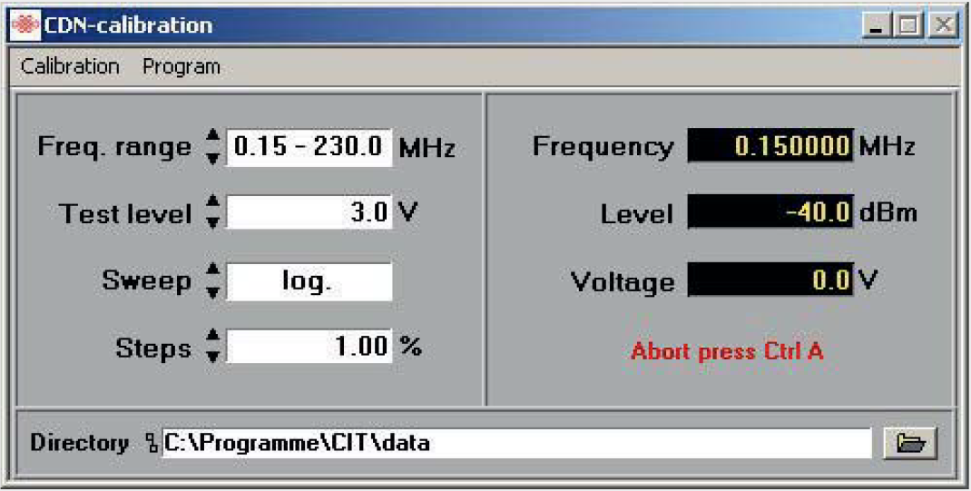
When selecting <Self-calibration>, the test equipment will perform a self-calibration. In this case, the output of the signal generator must be connected to the input of the voltmeter.
Functioning
The equipment is ready for operation immediately after connection with the USB port and installation of the drivers and the control software. After starting the control software, the main menu offers the manual control of <RF-Generator> and <RF-Power Meter>. Further options in the menu are <Calibration> (1) (<CDN-Calibration>, <Self-Calibration>) and <Test> (2) (<Complete Test>, <Selective Test>).
Test (2)
The menu option <Test> offers the selection possibilities <Complete Test>, <Selective Test> and <Protocol>. The settings for a test, e.g. start and stop frequency, step width and test voltage are made automatically via the calibration file of the selected coupling unit. It is now possible to decide whether the test is to be performed exactly according to these pre-settings, i.e. exactly as in the calibration, or whether modifications of the pre-settings shall be admissible. If the calibration run was performed, for example, for a test voltage of 10 V, and the test is to be performed now with 3 V without having to perform a new calibration run for this purpose, this can be done by selecting menu item <Extrapolation>.
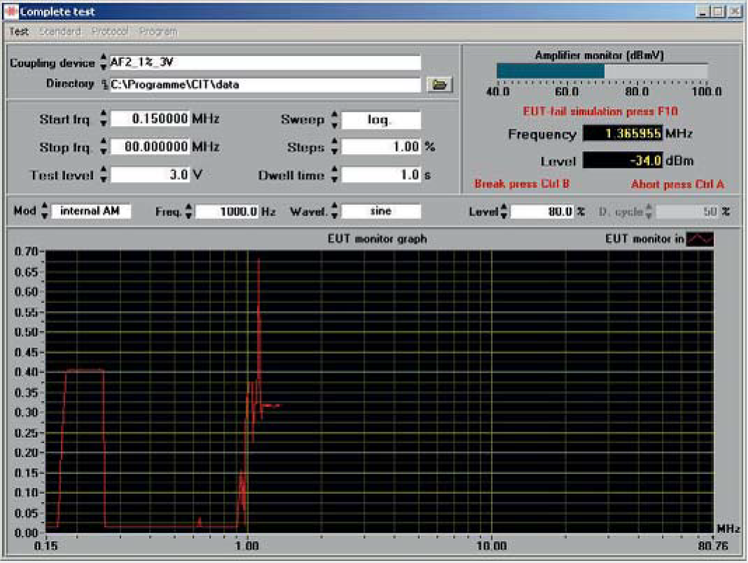
Is a suitable measuring instrument connected to the specified serial port of the CIT-10, EUT can be monitored automatically. Data are shown graphically. During all test routines the amplifier output is monitored in a bar display. This guarantees correct tests. In the case of <Complete Test>, a test is performed over the complete selected frequency range; in this case the test frequency is increased by the control software according to the selected step width and the
entered dwell time. If there is a malfunction of the EUT, the test may be stopped at any time. It is then possible to either increase or reduce the frequency by any number of steps, as well as to switch on and off the modulation and test voltage. Besides, a description of the malfunction occurred may be entered in a comment line which is included in the test record.
<Selective Test> offers the possibility of testing the EUT at discrete frequencies. This can be done either with a fixed test voltage or, optionally, with a ramp function. In case of the ramp function, the start and stop voltage, the step width by which the test voltage is to be increased, as well as the dwell time between the individual steps may be preset by the tester.
The standard <Protocol> consists of the head of the protocol and a diagram which shows the test results. In the head of the protocol the date and time are taken over from the computer; in addition, details like temperature, air humidity, tester, as well as testing set-up and EUT, may be registered. The protocol may be printed directly. It is also possible to edit the protocol individually.
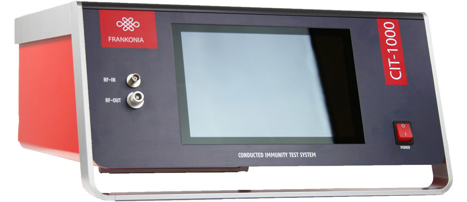
CIT-1000
The CIT-1000 is a further development of the for years available and proven „CIT-10“, with the extended frequency range up to 1200MHz, stand-alone-operation via integrated Touch-Screen-PC as well as integrated directional coupler and power-meter for forward and reverse power measurement.
As usual with our CIT-series, all integrated instruments, like Signalgenerator, RF-Power-Amplifier and the 3-channel-RF Power Meter can be used as „stand-alone-unit“, too.
Hence, the Signal-generator and the RF-power-meter can also be used for radiated immunity tests acc. IEC/EN 61000-4-3. Furthermore an additional external RF-Power-amplifier could be connected to the CIT-1000 for this purpose.
Special Features
Technical specifications
| RF-Generator | CIT-1000 |
| Two switchable outputs (only one can be used simultaneously) | 2 x SMA |
| Frequency range | 9 kHz to 1.2 GHz |
| Frequency resolution | 1 Hz |
| Output level range | 0 to -63 dBm |
| Output level resolution | 0.1 dB |
| Harmonics | < 30 dBc |
| Spurious | < 45 dBc |
| Amplitude modulation (internal) | 0 to 100%, resolution 1% |
| Amplitude modulation (external) | 0 to 100% , max. Amplitude 1V = 100%, BNC jack |
| Pulse modulation (internal) | 5 to 95%, resolution 1% |
| Pulse modulation (external) | DC…1MHz, 3,3/5V CMOS/TTL, BNC jack |
| LF-Generator (modulation) | CIT-1000 |
| Connector | BNC jack |
| Frequency range | 1 Hz to 100 kHz |
| Frequency resolution | 0.1 Hz |
| Signal | Sine wave / square wave / triangular |
| Amplitude | 0…1 V |
| RF-Voltmeter 1 (test level) | CIT-1000 |
| Connector | BNC jack |
| Frequency range | 9 kHz to 1.2 GHz |
| Measuring range | -40 to +30 dBm |
| RF-voltmeter 2+3 (forward and reverse power) | CIT-1000 |
| Connector | 2 x SMA |
| Frequency range | 9 kHz to 1.2 GHz |
| Measuring range | -40 to + 33 dBm + directional coupler typ. 40 dB |
| EUT-Monitor input | CIT-1000 |
| input voltage | 0 to 10 V DC |
| resolution | 2.5 mV |
| Input impedance | 100 Ω |
| EUT-failed input | CIT-1000 |
| Input signal | 3,3/5V CMOS/TTL level |
| Detection mode | status or edge controlled |
| Temperature measurement | 10 to 100 °C (1039 to 1385 Ω) resolution < 1 °C (PT 1000) |
| SCPI interfaces | CIT-1000 |
| USB 2.0 | USB-B |
| LAN, 100 Mbit | RJ45 |
| GPIB (optional) | Centronics |
| Digital I/Os | CIT-1000 |
| Out | 4 Bit Digital out, 5 V CMOS/TTL |
| In | 4 Bit Digital in, 5 V CMOS/TTL |
| Interlock | CIT-1000 |
| Closes at | R < 1 kΩ |
| Dimensions (mm) |
48x25x51,5 (LxHxD) |
| Weight | 18kg |