Emission measurements
EMI-Receiver
Antennas
Accessories
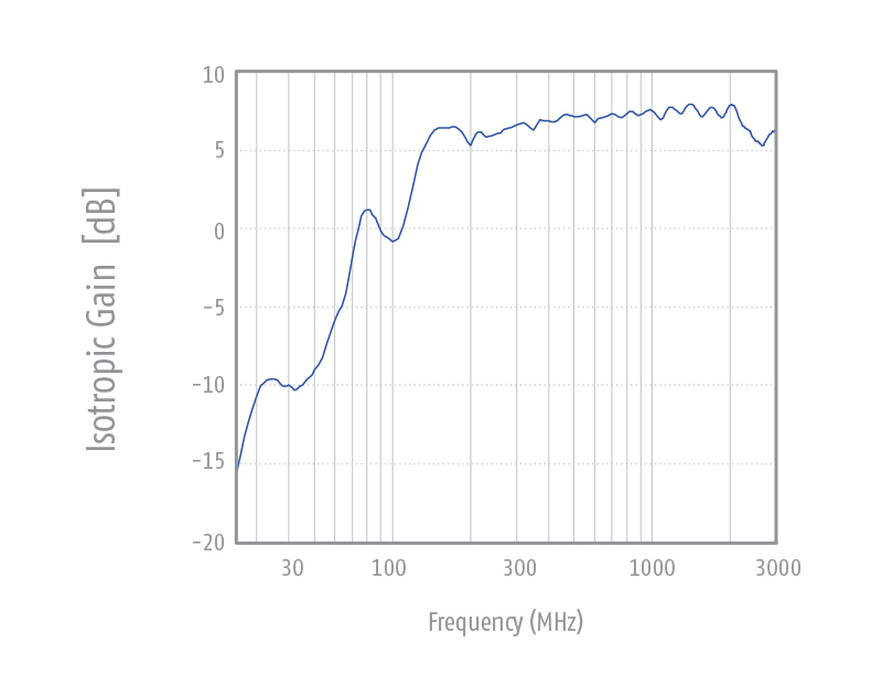
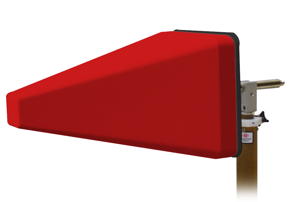
Broadband Antenna
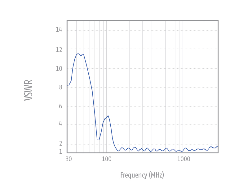
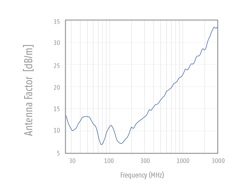
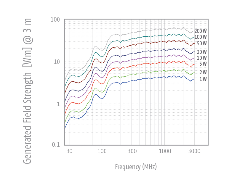
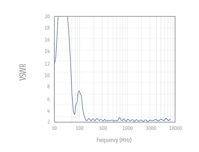
The ALX-4000E is an especially optimized version for emission measurements. It offers lower antenna factors and improved VSWR. Additionally it can be used for immunity tests which require an input power of less than 100 W cw (200W intermitt.).
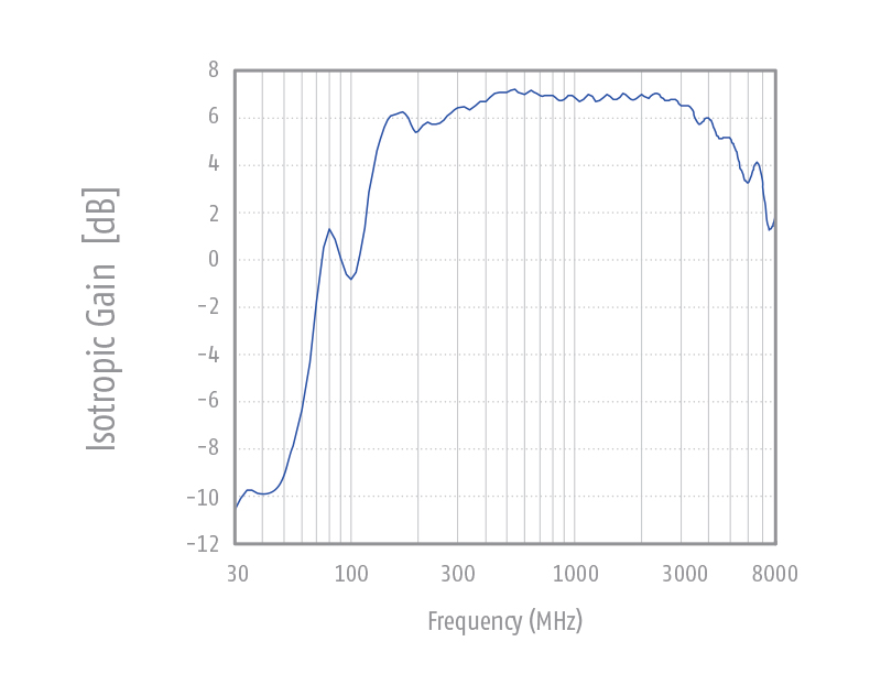
The ALX-8000E has an extended frequency range up to 8 GHz. All antennas are supplied with antenna factors for 3.0 m and 10.0 m measuring distance (1.0 m on request).

| Technical specifications | ALX-4000E |
| Frequency range | 25 MHz to 4 GHz |
| Max. input power | 200 W (intermtt.) 100 W (cont.) |
| Nominal impedance | 50 Ω |
| Connector | type N female |
| Isotropic gain (LP-Section) | 6.4 +/- 1.2 dBi |
| Antenna factor | 7 … 34 dB/m |
| Standing wave ratio SWR typ. | < 1.5 |
| Front to back ratio | 20 dB (f > 150 MHz) |
| Cross polarization | >20 dB (30 MHz…1 GHz) |
| 3 dB beamwidth typ. (E-Plane) | 45°-65° (f > 150 MHz) ≈ 78° (f < 150 MHz) |
| 3 dB beamwidth typ. (H-Plane) | 90°-120° (f > 150 MHz) |
| Dimensions (W x L x D) | 1500 x 910 (1240) x 620 mm |
| Weight | 3.1 kg |
| Fixation (indexing ring) | 22 mm tube |
| Use | Radiated immunity tests Emission measurements |
| Technical specifications | ALX-8000E |
| Frequency range | 25 MHz to 8 GHz |
| Max. input power | 200 W (intermtt.) 100 W (cont.) |
| Nominal impedance | 50 Ω |
| Connector | type N female |
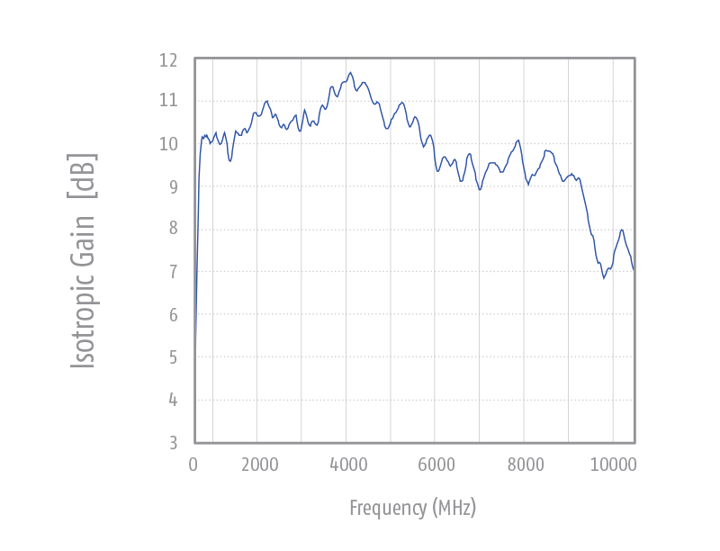
| Isotropic gain (LP-Section) | 6.4 +/- 1.2 dBi |
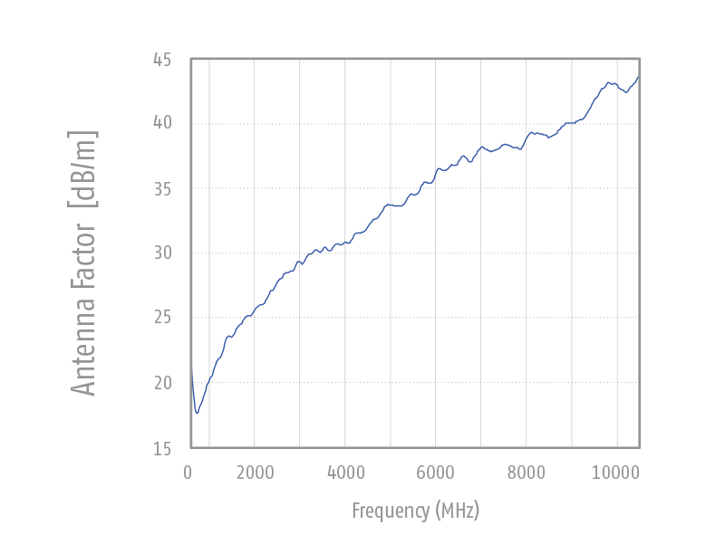
| Antenna factor | 7 … 43 dB/m |
| Standing wave ratio SWR typ. | < 1.5 (f > 150MHz) |
| Front to back ratio | 20 dB (f > 150 MHz) |
| Cross polarization | >20 dB (30 MHz…1 GHz) |
| 3 dB beamwidth typ. (E-Plane) | 45°-65° (f > 150 MHz) ≈ 78° (f < 150 MHz) |
| 3 dB beamwidth typ. (H-Plane) | 90°-120° (f > 150 MHz) |
| Dimensions (W x L x D) | 1500 x 920 (1253) x 620 mm |
| Weight | 3.1 kg |
| Fixation (indexing ring) | 22 mm tube |
| Use | Radiated immunity tests Emission measurements |


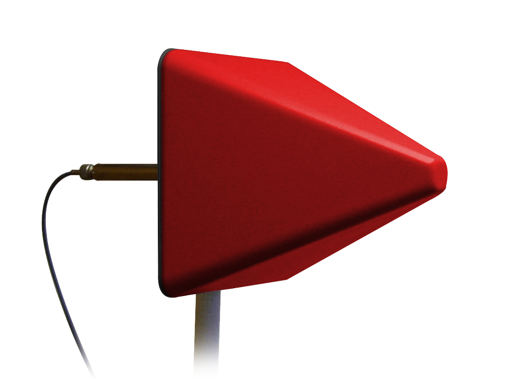
Stacked Log.-periodic Antenna
Stacked logarithmic-periodic broadband antenna for radiated immunity tests and emission measurements in the microwave frequency range. The antenna structure is made of laser-cut brass.
For protection of the fine antenna structure against damage the antenna is equipped with a low loss plastic protection cover. The MAX-9 is especially suitable for immunity testing acc. to IEC 61000-4-3 because of its good field uniformity. Further outstanding characteristics of the MAX-9 are the wide bandwidth, the nearly constant high gain, very good impedance matching as well as equal beamwidth in E- and H-plane.
| Technical specifications | MAX-9 |
| Frequency range | 600 MHz – 10.5 GHz |
| Max input power | 300 W (f = 1 GHz) 150 W (f = 6 GHz) |
| Nominal impedance | 50 Ω |
| Connection | type N female |
| Isotropic Gain | typ. 10.3 dBi ± 1.5 dB |
| Antenna factor | 18 … 41 dB/m |
| SWR typical | < 1.5 (f < 7 GHz) |
| Front to back ratio | > 25 dB typ. |
| Cross polarization rejection | > 30 dB typ. |
| Half-power beamwidth (E-Plane) | 46° ± 10° |
| Half-power beamwidth (H-Plane) | 48° ± 10° |
| Dimensions (W x L x D) in mm | 460 (+215) x 270 x 270 |
| Weight | 3.7 kg |
| Fixation | Ø 22mm mounting tube |
| Use | Radiated immunity tests Emission measurements |
Technical specifications MAX-9-7/16
Same specifications as above with the following changes:
Frequency Range: 0.6 GHz – 7.5 GHz
Isotropic Gain: typ. 10.3 dBi,(0,6)0,7-7,5 GHz
Max. Input Power: 380 W (f = 5 GHz) | 950 W (f = 1 GHz)


Stacked logarithmic-periodic broadband antenna for radiated immunity tests and emission measurements in the microwave frequency range. The antenna structure is made of laser-cut brass.
For protection of the fine antenna structure against damage the antenna is equipped with a low loss plastic protection cover. The MAX-18 is especially suitable for immunity testing acc. to IEC 61000-4-3 because of its good field uniformity. Further outstanding characteristics of the MAX-18 are the wide bandwidth, the nearly constant high gain, very good impedance matching as well as equal beamwidth in E- and H-Plane.
| Technical specifications | MAX-18 |
| Frequency range | 700 MHz – 20 GHz |
| Max input power | 50 W |
| Nominal impedance | 50 Ω |
| Connection | type N female |
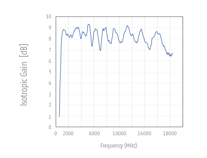
| Isotropic Gain | typ. 8.6 dBi ± 1 dB |
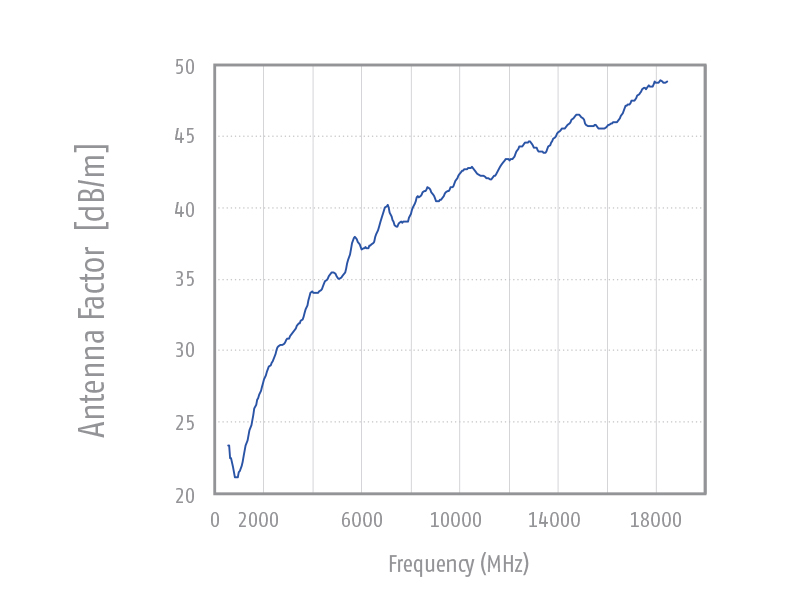
| Antenna factor | 20 … 49 dB/m |
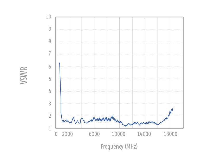
| SWR typical | < 2 |
| Dimensions (W x L x D) in mm | 490 x 270 x 270 |
| Weight | 1.2 kg |
| Front to back ratio | > 25 dB typ. |
| Cross polarization rejection | > 28 dB typ. |
| Half-power beamwidth (E-plane) | 58° |
| Half-power beamwidth (H-plane) | 60° |
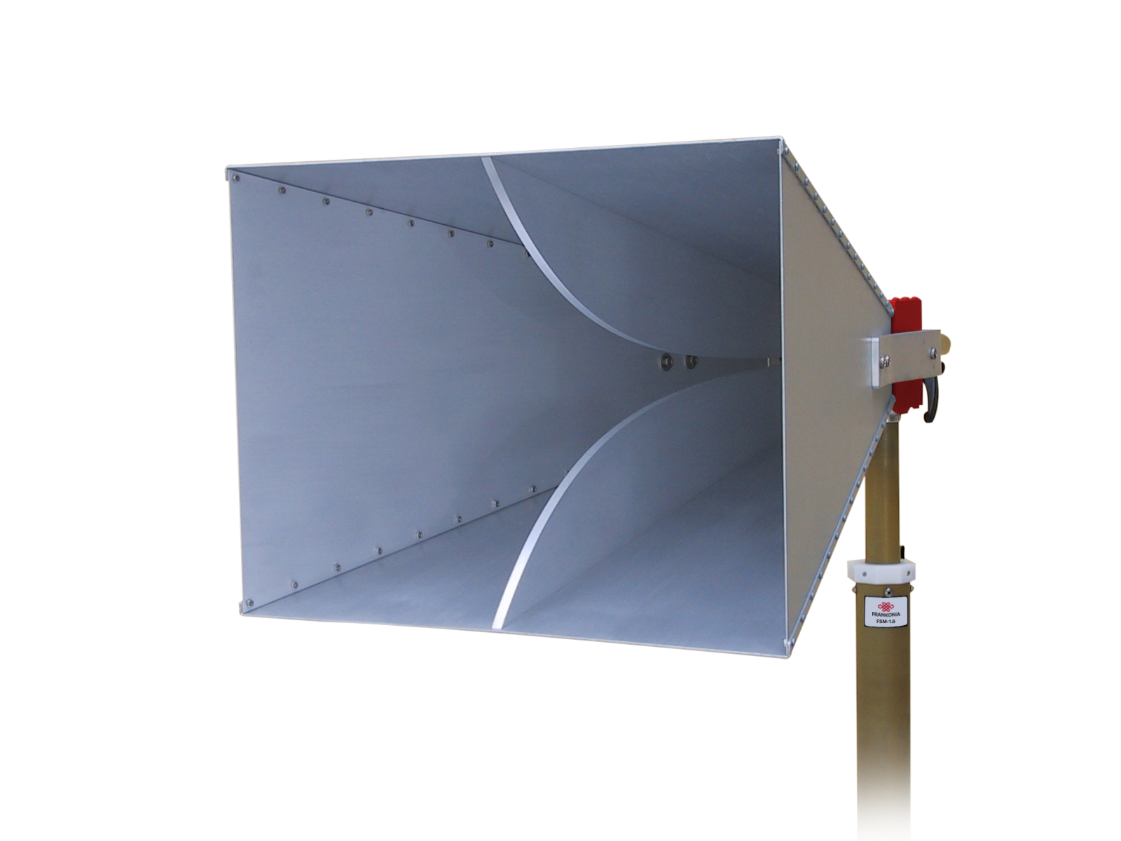
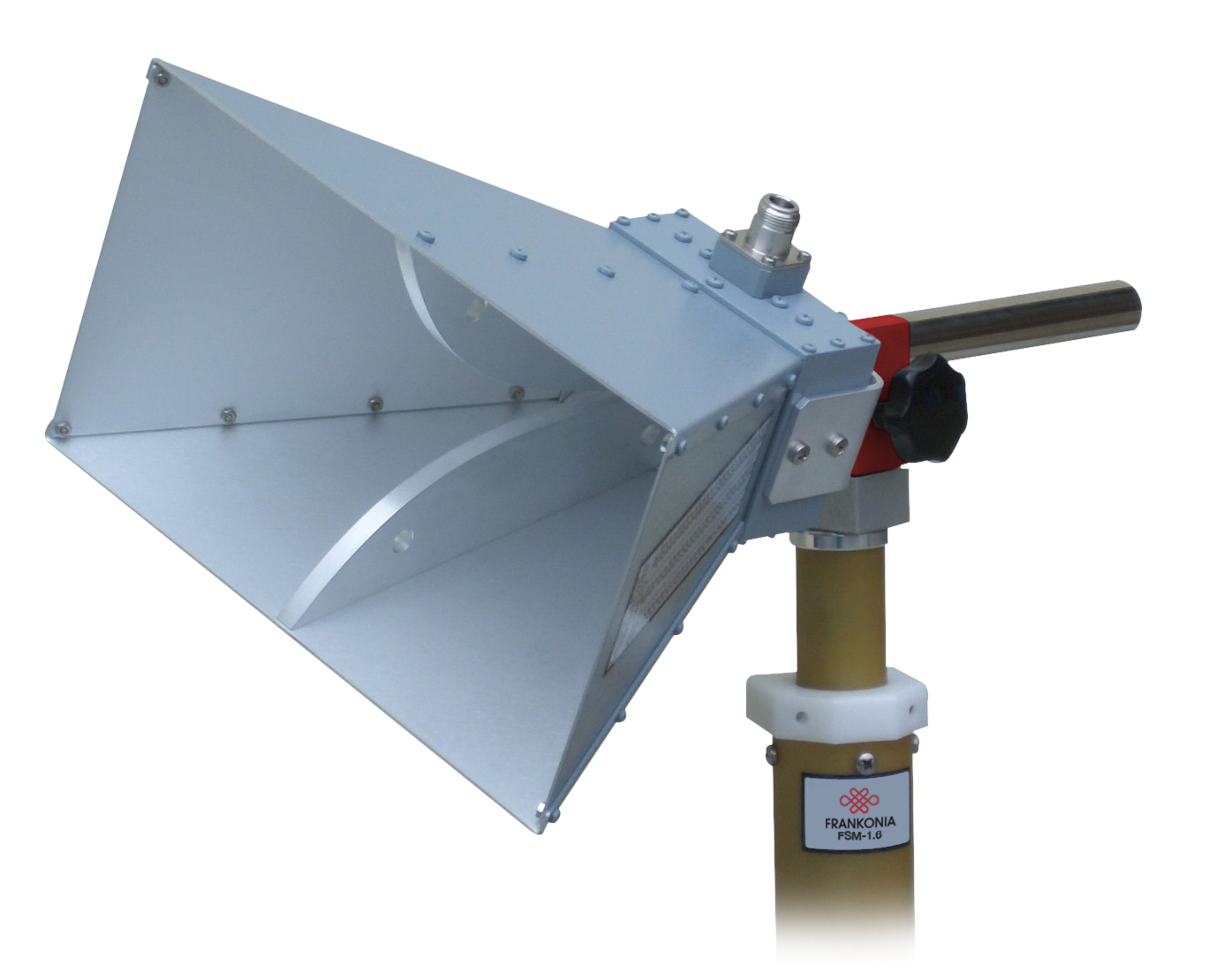
Broadband Horn Antenna
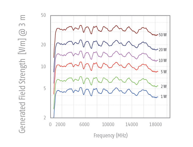
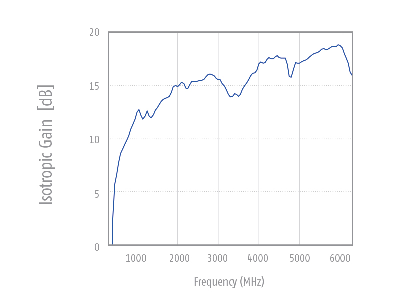
The horn antennas HAX offer a very low SWR in their nominal frequency range and a very broad bandwidth. The gain increases with frequency up to approx. 18 dBi. The increasing gain with frequency helps to compensate cable losses.
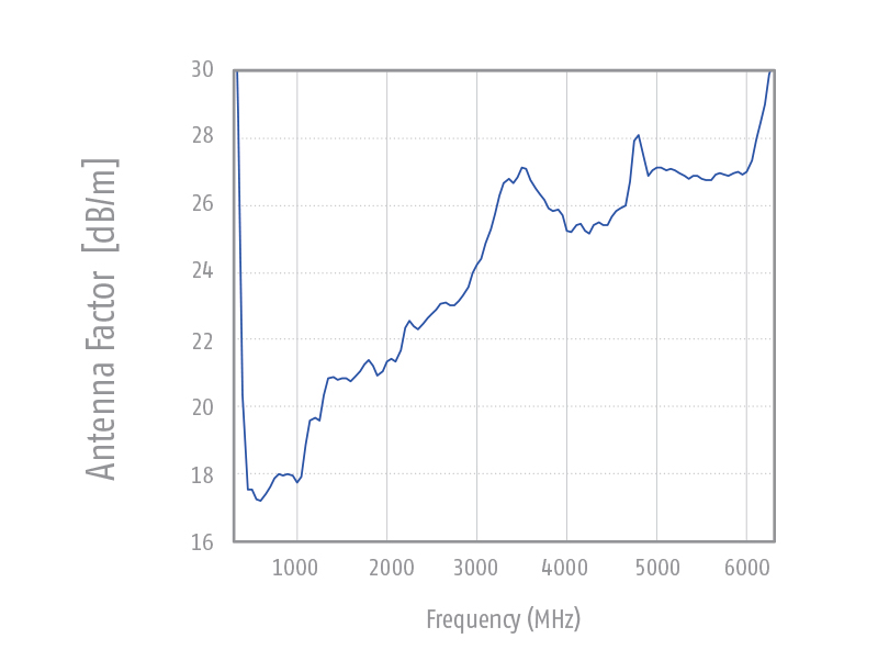
The HAX series is suitable for both, transmission and receiving applications. The maximum allowed input power is only limited by the female N-connector. The detailed manual of the calibrated test antennas includes gain, antenna factor, SWR and directional patterns. The antenna is mounted with the 22 mm tube, equipped with a index ring for quick changes of polarization without using tools.
| Technical specifications | HAX-6 |
| Frequency range | 500 MHz – 6 GHz |
| Max input power | limited only by N-connector |
| Connection | type N female |
| Gain | 6 … 18 dBi |
| Antenna factor | 19 … 29 dB/m |
| Standing wave ratio SWR typ. | < 2 |
| Dimensions (W x L x D) in mm | 424 x 314 x 820 |
| Weight | 4.1 kg |
| Fixation | Ø 22mm mounting tube |
| Material | aluminium |
| Use | Radiated immunity tests Emission measurements |


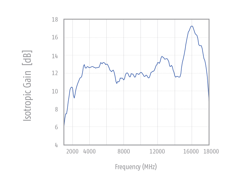
The horn antennas HAX offer a very low SWR in their nominal frequency range and a very broad bandwidth. The gain increases with frequency up to approx. 16 dBi. The increasing gain with frequency helps to compensate cable losses.
The HAX series is suitable for both, transmission and receiving applications. The maximum allowed input power is only limited by the female N-connector. The detailed manual of the calibrated test antennas includes gain, antenna factor, SWR and directional patterns. The antenna is mounted with the 22 mm tube, equipped with a index ring for quick changes of polarization without using tools.
| Technical specifications | HAX-18 |
| Frequency range | 800 MHz – 18 GHz |
| Connection | N-female |
| Isotropic Gain | 6 … 18 dBi |
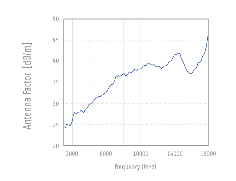
| Antenna factor | 24 … 50 dB/m |
| Nominal impedance | 50 Ω |
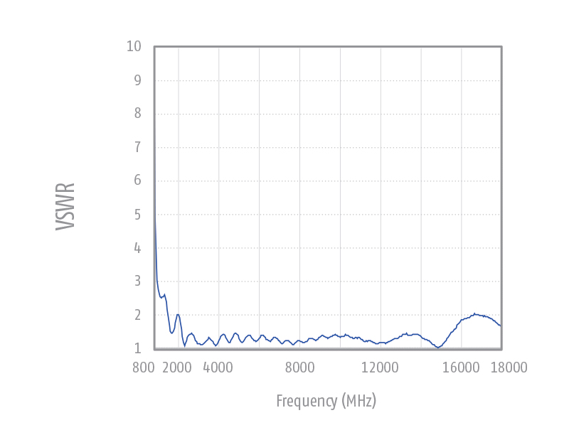
| SWR typical | ≈1.5 |
| Front to back ratio | > 25 dB (f > 1.3 GHz) |
| Cross polarization rejection | > 25 dB (1 GHz … 18 GHz) |
| 3 dB Beamwidth typ. (E-plane) | 90°-10° |
| 3 dB Beamwidth typ. (H-plane) | 60°-10° |
| Dimensions (W x L x D) in mm | 245 x 195 (408) x 142 |
| Weight | 1.3 kg |
| Fixation | Ø 22mm mounting tube |
| Use | Radiated immunity tests Emission measurements |

The horn antennas HAX offer a very low SWR in their nominal frequency range and a very broad bandwidth. The gain increases with frequency up to approx. 16 dBi. The increasing gain with frequency helps to compensate cable losses.
The HAX series is suitable for both, transmission and receiving applications. The maximum allowed input power is only limited by the female N-connector. The detailed manual of the calibrated test antennas includes gain, antenna factor, SWR and directional patterns. The antenna is mounted with the 22 mm tube, equipped with a index ring for quick changes of polarization without using tools.
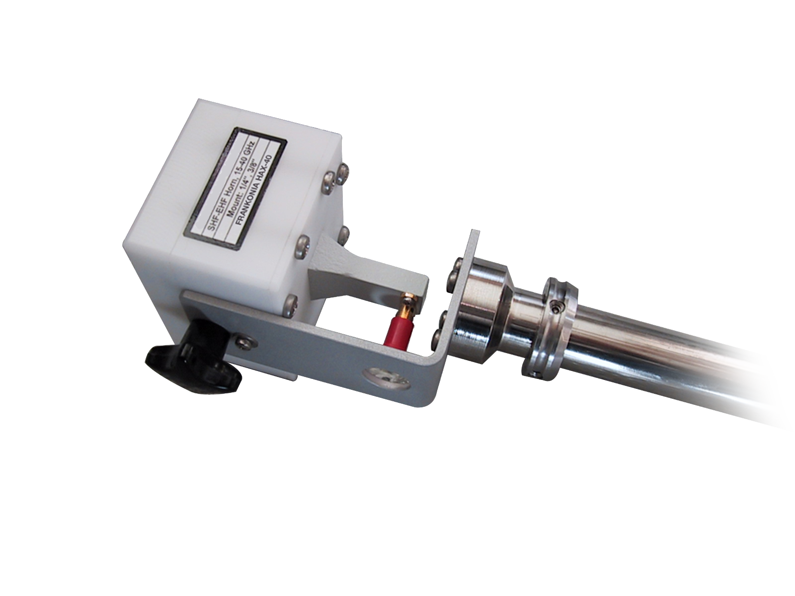
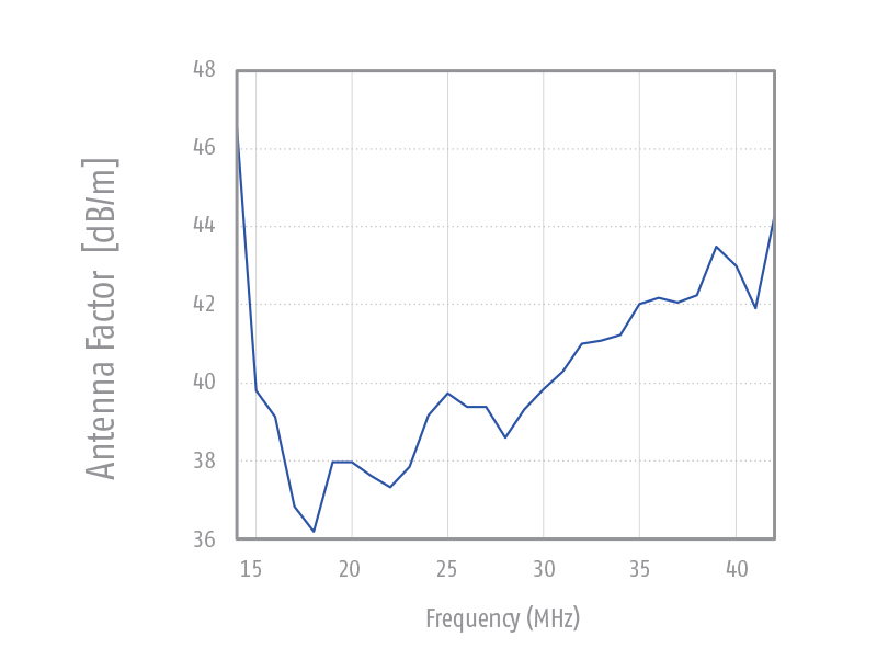
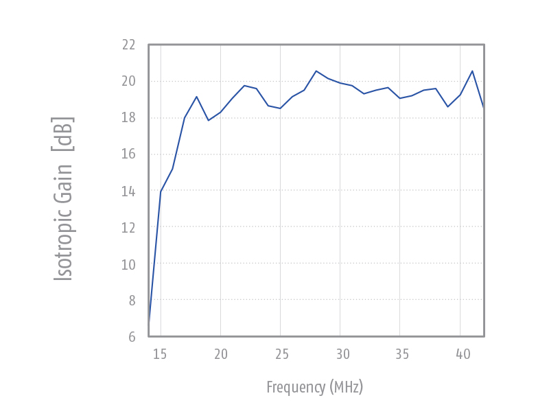
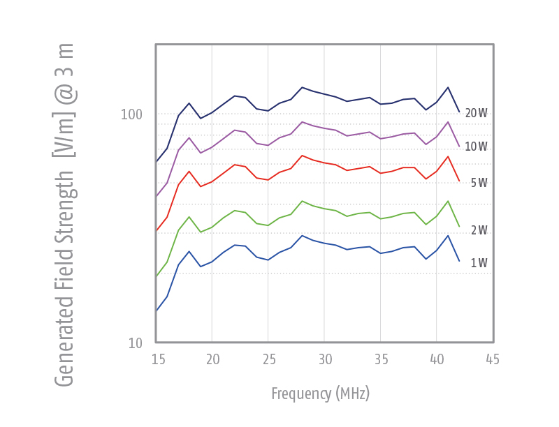
| Technical specifications | HAX-40 |
| Frequency range | 14 GHz – 40 GHz |
| Max input power | 10 W (cont.) 25 W peak |
| Connection | SMA-compatible | female |
| Isotropic Gain | 15 … 20 dBi |
| Antenna factor | 38 … 45 dB/m |
| SWR typical | ≈ 2 |
| Front to back ratio | > 30 dB |
| Cross polarization rejection | > 25 dB |
| 3 dB Beamwidth typ. (E-plane) | 13° – 21° |
| 3 dB Beamwidth typ. (H-plane) | 14° – 23° |
| Dimensions (W x L x D) in mm | 75 x 86 x 60 |
| Weight | 0.3 kg |
| Fixation | 3/8″, 1/4″ |
| Use | Radiated immunity tests Emission measurements |
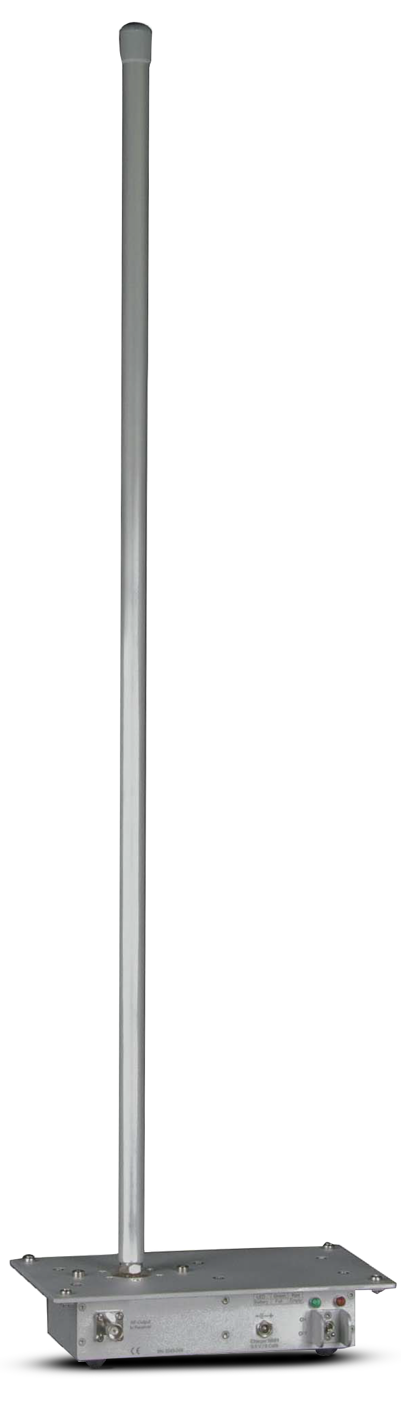
Active Rod Antenna
The active monopole antenna SAX-10 consists of a vertical rod and an impedance matching amplifier. The rod has a standard length of 1m (other rod length on request) and can be considered as short compared to the wave length in the frequency range 9 kHz-30MHz. The conversion factor is independent of the frequency because of the extremely high impedance of the matching amplifier. The circuit gives best results of noise and intermodulation for a conversion factor (antenna factor) of +10 dB and sensitive measuring receivers are able to use the whole dynamic range of the antenna. For very high field strength, an optional plug-in attenuator reduces the amplification by 20 dB.
In order to avoid absolutely any influence by the mains, power supply, voltage regulator a. o., the SAX-10 has built-in NiMH rechargeable batteries. The typical operation time is at least 50 hours. Charging time is 2-4 hours using the quick charger.
Rod antenna and amplifier cabinet are made of aluminium. The top plate can be fixed to the metal ground plane (counterpoise) with 4 screws. The connectors and controls are situated below the two plates. The rod length begins exactly at the top plate.
| Technical specifications | SAX-10 |
| Frequency range | 9 kHz – 30 MHz |
| Antenna factor | +10 dB/m ± 1.5 dB |
| Upper limit of field strength measurement | 1 V/m (F=1 MHz, 1 dB compression) Input attenuator for higher field strength optional |
| Lower limit of field strength measurement | Limitation by internal noise: Typ. -3 dBμV/m / 10 MHz, CISPR-Quasipeak, 9 kHz bandwidth Typ. -8 dBμV/m / 10 MHz, average detector, 9 kHz bandwidth |
| Output of the monopole amplifier | BNC-connector, fem., 50 Ω nom. |
| Power supply | 9.6 V / 1100 mAh NiMH |
| Dimensions and weight | Length including thread connection 1 m, weight approx.: 0.2 kg |
| Monopole (rod) | 180 x 80 x 40 mm (WxHxD) without BNC-connector (female) and controls. |
| Amplifier | Top plate 220 x 120 mm, weight approx.: 0.7 kg |
| Construction of the monopole (rod) | Aluminium rod 16 mm diameter with thread-hole M8 |
| Construction of the amplifier | Cabinet made of aluminium profiles. Top plate 3mm aluminium material |
| Threads for tripods | 1/4″, 3/8″ |
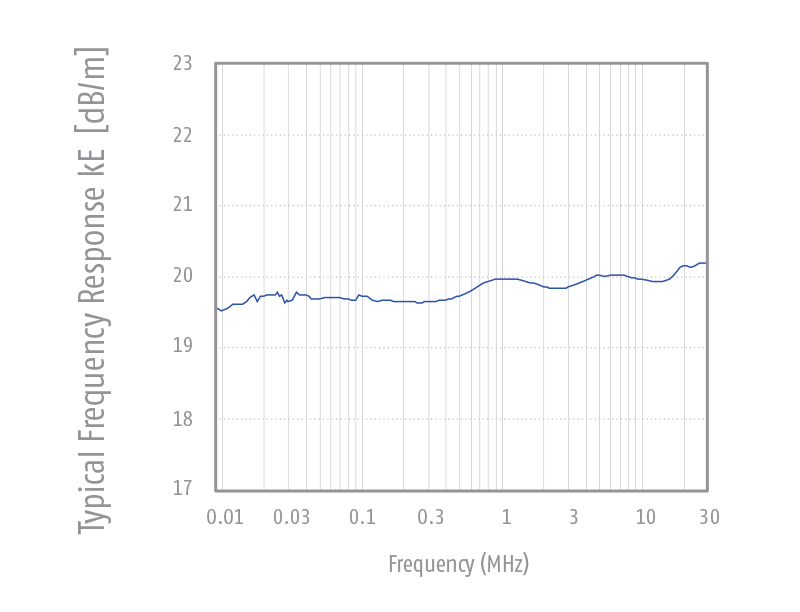
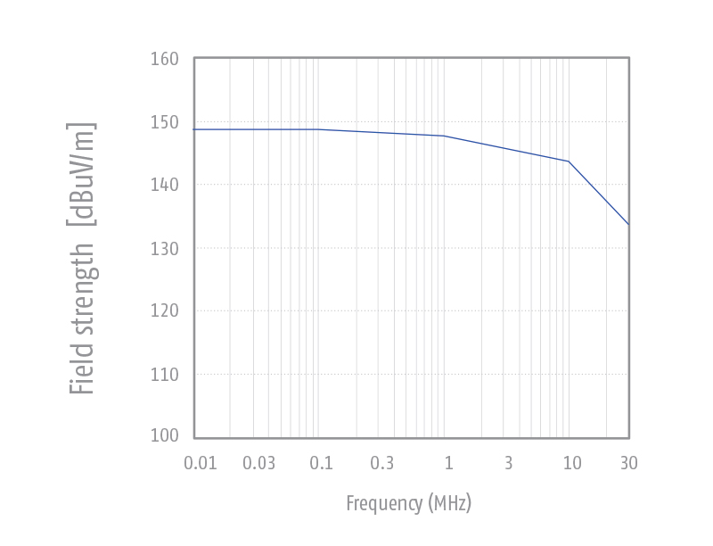
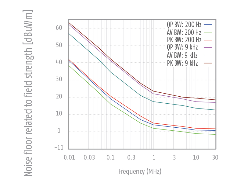
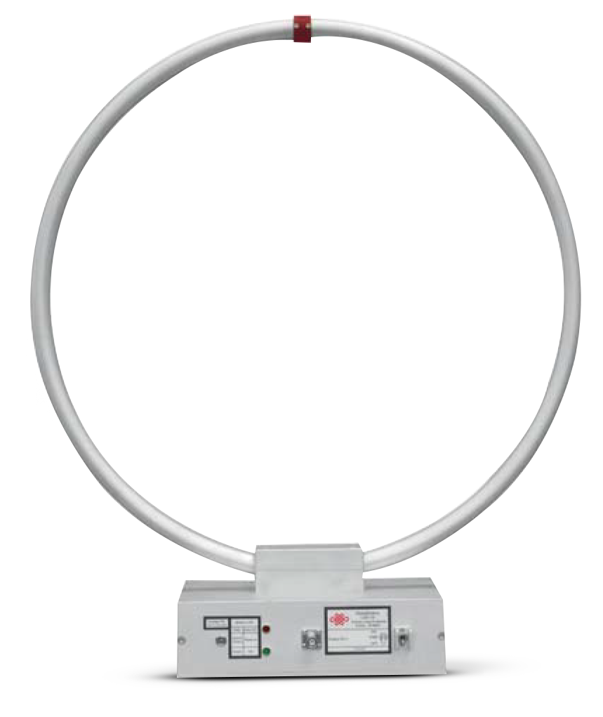
Active Loop Antenna
Active, shielded loop antenna with nearly constant antenna factor over the entire frequency range, battery driven to minimize disturbance influence from power line. Combined with a CISPR-16 EMI-receiver a convenient field strength measuring system with low noise and pulse measuring capabilities is composed. The LAX-10 can also be used with a spectrum analyzer. The shielded aluminum housing is equipped with rubber feet for desktop operation or can be mounted to a tripod using the female camera thread (3/8”) at the bottom. A protection circuit against deep discharge provides a long battery lifecycle. The battery must be recharged after an automatic switch off.
A full battery charging period using the recommended charger takes around 5 hours. The PWR-switch must be set to OFF during the recharging period, otherwise no charging takes place. The charging connector is disabled while the PWR switch is set to ON (normal measuring operation), this avoids disturbances generated by the charger having an unwanted influence on the measurement.
The active loop antenna LAX-10 can be used for the frequency selective measurement of magnetic fields in the long wave, mid wave and short wave frequency ranges. It can be used for testing according to CISPR, MIL, FCC, EN, ISO, ANSI, ETSI and many other standards.
| Technical specifications | LAX-10 |
| Nominal frequency range | 9 kHz – 30 MHz |
| Connector, female | 50 ohm, BNC |
| Antenna factor for fict. E-field strength | 20 dB / m |
| Antenna factor for H-field strength | -31.5 dB / Ω |
| Loop diameter | 0.5 m |
| Fieldstrength measuring range QP-Detector / 9 kHz IF-Bandwidth | 30 – 130 dBμV/m |
| Fieldstrength measuring range AV-Detector / 200 Hz IF-Bandwith | 8 – 130 dBμV/m |
| Operation time with full battery capacity | typ 12h |
| Battery capacity | 12 V NiMH 1.9 AH |
| Recommended charger | ACS 110 |
| Mounting thread | 1/4”, 3/8” |
| Dimensions (W x L x D) in mm | 520 x 585 x 120 |
| Weight | 1.9 kg |