Relay-Switching-Unit
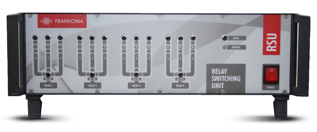
The RSU RF-Relay Switching Unit is applicable for all fields of RF- and EMC measurements to switch (manual or remote controlled) from one input to 2 or 3 outputs. Typical applications in measuring systems are changeover switching between different amplifiers, antennas or power meters. This does also prevent circuit faults due to wrong cabling. By means of a selector switch on the front panel of the RSU it is possible to work in manual mode or remote control mode via the RS232, USB or GPIB interface.
The input/output connectors of the relays are installed on the rear panel of the RSU, this allows an easy cabling when or where the RSU is mounted into a 19”-rack. A RSU can be equipped with a maximum of 4 relays with 2 or 3 outputs. The quantity of relays with 2 or respectively 3 outputs is variable. The delivery includes a Windows software for easy remote controlled applications. However for extensive systems it is recommended to integrate the RSU driver into the system control software.
The easy to follow commands for RS232 and GPIB interfaces are listed in the user manual.
Definition of the relay assembly

| Technical specifications | RSU | |||
| Frequency range | DC to 12.4 GHz (up to 18 GHz or 40 GHz optional) | |||
| Test level | 50 V cont., 300 V (1s) at energetically used frequencies | |||
| DC…1GHz | 1 GHz…5 GHz | 5 GHz…10 GHz | 10 GHz…12.4 GHz | |
| VSWR | < 1.04 | < 1.14 | < 1.3 | < 1.5 |
| Isolation | > 90 dB | > 80 dB | > 70 dB | > 70 dB |
| Insertion loss | < 0.05 dB | < 0.1 dB | < 0.2 dB | < 0.3 dB |
| Max. power input | < 1.00 kW | < 0.44 kW | < 0.31 kW | < 0.28 kW |
| Impedance | 50 Ohm | |||
| Rf-connectors / Relays | N-Female | |||
| Switching time | < 60 ms | |||
| Number of operations | Max. 10/Minute | |||
| Operating temperature | +10°C… +40°C | |||
| Max. humidity | < 90% | |||
| Cabinet | 19″-subrack or desktop case | |||
| Dimensions (D x W x W) | 435.5×448.9×132.55mm | |||
| Weight | 7.6kg | |||