Amplifiers
Accessories
Immunity to conducted disturbances, induced by radio-frequency fields
-
IEC 61000-4-6
Bulk Current Injection (BCI)
-
ISO 11452-4
-
MIL-STD 461E, CS 114
Testing devices:
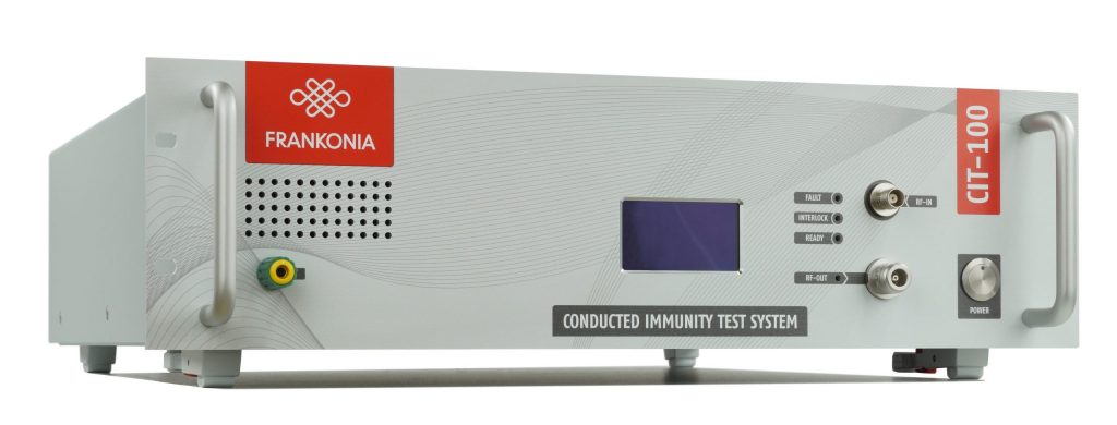
Compact Immunity Test System
The CIT-100 is a complete test system for conducted RF-immunity testing and BCI-testing acc. to IEC/EN 61000-4-6, ISO 11452-4, MIL-STD 461, CS114 and similar standards.
The system coconsists of a built-in
• Signal generator, 4kHz – 1.2 GHz
• RF-Power-Amplifier. max 4kHz – 400 MHz, 25 / 75 W
• 3-Channel RF-Power-Meter to measure the test level as well as forward & reverse power, 4kHz – 1.2 GHz
• Directional Coupler
• Comfortable control software
As a „stand-alone“ test system the CIT-100 is convincing by its easy and comfortable handling and the excellent cost-performance ratio.
We also offer the full range of coupling/decoupling networks (CDN‘s) ,
EM-coupling clamp, BCI- and current clamps.
Special Features
Technical specifications
| RF-Generator | CIT-100 |
| Two switchable outputs (only one can be used simultaneously |
2 x SMA |
| Frequency range | 4 kHz to 1.2 GHz |
| Frequency resolution | 1 Hz |
| Output level range | 0 to – 63 dBm |
| Output level resolution | 0.1 dB |
| Harmonics | < 30 dBc |
| Spurious |
< 45 dBc |
| Amplitude mod. (internal) |
0 – 100%, resolution 1% |
| Amplitude mod. (external) | 0 – 100%, max Amplitude 1V = 100%, BNC jack |
| Pulse mod. (internal) |
5-95%, resolution 1% |
| Pulse mod. (external) | DC…1MHz, 3,3V/5V CMOS/TTL, BNC jack |
| LF Generator (modulation) |
CIT-100 |
| Connector | BNC jack |
| Frequency range | 1 Hz to 100 kHz |
| Frequency resolution | 0.1 Hz |
| Signal | Sine wave / square wave / triangular |
| Amplitude | 0…1 V |
| SCPI interfaces |
|||
| USB 2.0 |
USB-B | ||
| LAN, 100 Mbit |
RJ45 | ||
| GPIB (optional) |
Centronics | ||
Technical specifications
| RF-Voltmeter 1 (test-level) |
CIT-100 | ||
| Connector |
BNC jack | ||
| Frequency range |
4 kHz to 1.2 GHz | ||
| Measuring range |
-40 to +30 dBm | ||
| RF-Voltmeter 2 + 3 (test-level) |
(forward and reverse power) |
||
| Connector |
2x SMA | ||
| Frequency range |
4 kHz to 1.2 GHz | ||
| Measuring range |
-40 to +30 dBm + directional coupler typ. 40dB |
||
| EUT-Monitor input) |
|||
| Input voltage |
0 – 10 V | ||
| Resolution |
2.5 mV | ||
| Input impedance |
100 k | ||
| EUT-failed input |
|||
| Input signal |
3.3 / 5 V CMOS/TTL level | ||
| Detection Mode |
Status or edge controlled | ||
| Temperature measurement |
10 to 100 °C resolution (1039-1385Ω) resolution < 1 °C (PT1000) |
||
| Digital I/Os |
|||
| Out |
4 Bit Digital out, 5 V CMOS/TTL | ||
| In |
4 Bit Digital in, 5V CMOS/TTL | ||
| Interlock |
|||
| Closes at |
R < 1 k Ω | ||
Features
Internal RF-Power Amplifier
Several amplifier modules are available. Highest output power can be 75 W over the specified frequency range. The amplifier input can be accessed via the back panel of the CIT-100, so that the amplifier can also be used with any external generator. 25 W and 75 W amplifiers are available as standard.
Amplitude Modulation
Frequencies generated by the generator can also be modulated with a LF signal. Modulation frequencies may vary from 1 Hz up to 100 kHz, modulation levels are available from 0 % to 100 %.
Internal RF-Voltmeter
Accurate measurements of RF signals from -40 dBm up to +30 dBm are done by the internal RF-voltmeter which can be accessed (for separate use) via a BNC connector. Two internal voltmeters measure the test level and two channels to measure the forward and reverse power via the built-in directional coupler.
Internal RF-Signal Generator
As the internal generator generates its output signal without any internal mixing components, low harmonics and spurious frequencies are assured.
User defined signals
External signals (e.g. EUT-fail or external instruments) can be connected and monitored using the application software.
Setup
The CIT-10 is a PC-controlled test equipment. It can be operated by any commercial IBM compatible PC (Microsoft® Windows software) via USB port. All settings of the equipment, e.g. start frequency, stop frequency,
step width, test voltage etc. are made by means of the control software which is also included in the delivery. The three functional units RF-signal generator, RF-power amplifier and RF-voltmeter are set automatically by the software, depending on the pre-set test parameters. Each component, however, may also be called and operated as separate measuring and testing equipment. This means: using the CIT-10 as testing system, you have three full, additional “single units” at your disposal, for which separate inputs and outputs are available as BNC connections. Due to the computer-aided control of the CIT-10, any modifications which may become necessary, for example, due to the revision of standards, may be performed without problems and without having to manipulate the hardware of the equipment.
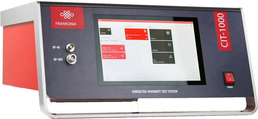
The CIT-1000 is a further development of the for years available and proven „CIT-10“, with the extended frequency range up to 1200MHz, stand-alone-operation via integrated Touch-Screen-PC as well as integrated directional coupler and power-meter for forward and reverse power measurement.
As usual with our CIT-series, all integrated instruments, like Signalgenerator, RF-Power-Amplifier and the 3-channel-RF Power Meter can be used as „stand-alone-unit“, too.
Hence, the Signal-generator and the RF-power-meter can also be used for radiated immunity tests acc. IEC/EN 61000-4-3. Furthermore an additional external RF-Power-amplifier could be connected to the CIT-1000 for this purpose.
Special Features
Technical specifications
| RF-Generator | CIT-1000 |
| Two switchable outputs (only one can be used simultaneously) | 2 x SMA |
| Frequency range | 9 kHz to 1.2 GHz |
| Frequency resolution | 1 Hz |
| Output level range | 0 to -63 dBm |
| Output level resolution | 0.1 dB |
| Harmonics | < 30 dBc |
| Spurious | < 45 dBc |
| Amplitude modulation (internal) | 0 to 100%, resolution 1% |
| Amplitude modulation (external) | 0 to 100% , max. Amplitude 1V = 100%, BNC jack |
| Pulse modulation (internal) | 5 to 95%, resolution 1% |
| Pulse modulation (external) | DC…1MHz, 3,3/5V CMOS/TTL, BNC jack |
| LF-Generator (modulation) | CIT-1000 |
| Connector | BNC jack |
| Frequency range | 1 Hz to 100 kHz |
| Frequency resolution | 0.1 Hz |
| Signal | Sine wave / square wave / triangular |
| Amplitude | 0…1 V |
| RF-Voltmeter 1 (test level) | CIT-1000 |
| Connector | BNC jack |
| Frequency range | 9 kHz to 1.2 GHz |
| Measuring range | -40 to +30 dBm |
| RF-voltmeter 2+3 (forward and reverse power) | CIT-1000 |
| Connector | 2 x SMA |
| Frequency range | 9 kHz to 1.2 GHz |
| Measuring range | -40 to + 33 dBm + directional coupler typ. 40 dB |
| EUT-Monitor input | CIT-1000 |
| input voltage | 0 to 10 V DC |
| resolution | 2.5 mV |
| Input impedance | 100 Ω |
| EUT-failed input | CIT-1000 |
| Input signal | 3,3/5V CMOS/TTL level |
| Detection mode | status or edge controlled |
| Temperature measurement | 10 to 100 °C (1039 to 1385 Ω) resolution < 1 °C (PT 1000) |
| SCPI interfaces | CIT-1000 |
| USB 2.0 | USB-B |
| LAN, 100 Mbit | RJ45 |
| GPIB (optional) | Centronics |
| Digital I/Os | CIT-1000 |
| Out | 4 Bit Digital out, 5 V CMOS/TTL |
| In | 4 Bit Digital in, 5 V CMOS/TTL |
| Interlock | CIT-1000 |
| Closes at | R < 1 kΩ |
| Dimensions (mm) |
48x25x51,5 (LxHxD) |
| Weight | 18kg |
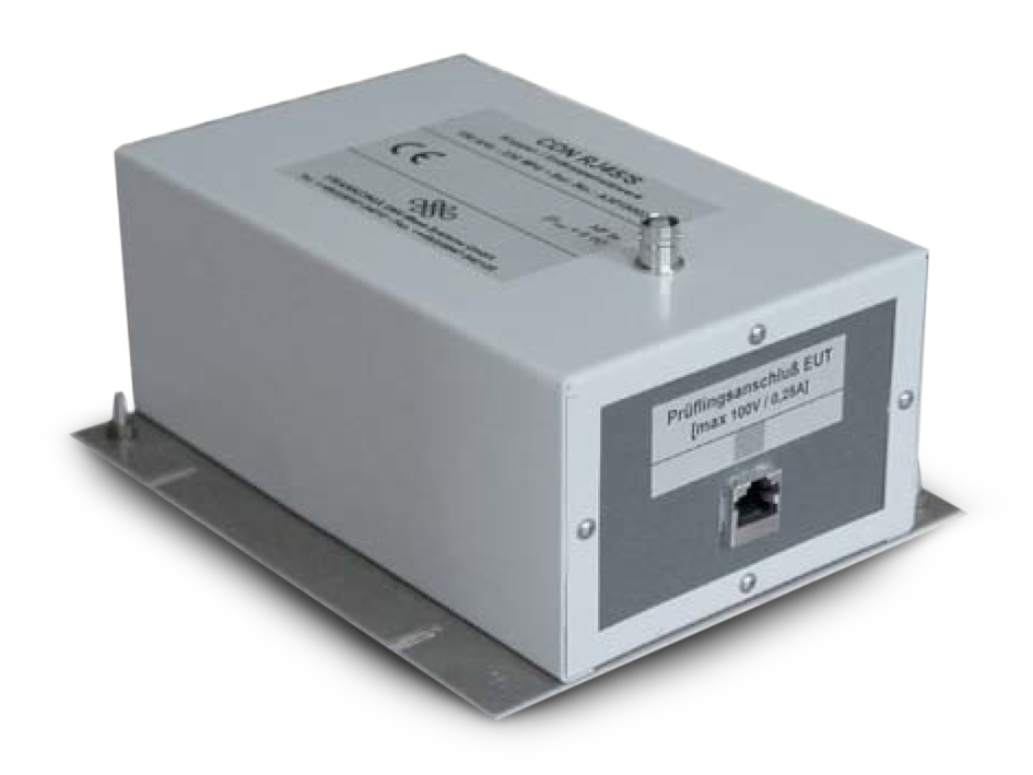
Coupling / Decoupling Networks
Immunity tests according to IEC/EN require coupling of RF disturbance voltages into any conducting cable of an EUT. Furthermore these disturbances should not be coupled into any further equipment so that a decoupling path to any auxiliary equipment is provided. We offer a wide range of CDNs for different types of interconnected lines which are fully calibrated for the frequency range from 150kHz to 230MHz. The following CDNs are available: M-, AF-, S-, T-, RJ, USB-types. Almost any network can be assambled on customer’s requests. Guidance for selecting the appropriate CDN is given in the following table:
| Type | Interconnected lines |
| M1, M2, M3, M4, M5, M2+M3 | Unscreened supply (mains) |
| AF2, AF4, AF5, AF6, AF8 | Unscreened nonbalanced lines |
| S1, S2, S4, S8, S9, S15, S25, S36 | Screened lines |
| T2, T4, T8 | Unscreened balanced lines |
| RJ11, RJ45 | Unscreened data lines |
| RJ11/S, RJ45/S, USB | Screened data lines |
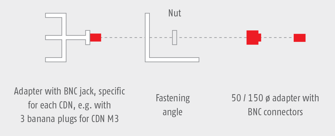
Calibration:
To calibrate a CDN an adaptor, a fastening angle and 50 Ω / 150 Ω adaptor are required. Fastening angle and 50 Ω / 150 Ω adaptor should be ordered for the first CDN. For each following CDN only the specific adaptor has to be ordered.
Test procedure with Coupling/Decoupling (CDNs) Networks acc. to IEC/EN 61000-4-6:
Set-up for level setting at the EUT-port of coupling and decoupling devices:
1. The test generator (RF-out) shall be connected to the RF-input port of the coupling device via the 6dB-attenuator.
2. The EUT port of the coupling device shall be connected in common-mode through the 150 Ω to 50 Ω adaptor to the RF-Voltmeters (calibration).
3. The AE-port shall be loaded in common-mode with a 150 Ω to 50 Ω adaptor, terminated with 50 Ω.
With direct injection to screened cable (CDN S-types), the 150 Ω load at the AE-port is not required as the screen will be connected to the ground reference plane at the AE-port side.
Although the 150 Ω load at the AE-port is mandatory with CDN T-, AF- and M-types calibration data are identical with the AE-port open or short. This is because a capacitor is connected to ground at the AEport side, which leads to a RF-short-circuit similar to the CDN S-types. This means that even with CDN M-, AF- and T-types the 150 Ω load at the AE-port is not required.
Coupling Clamp
According to IEC/EN 61000-4-6 the preferred coupling and decoupling devices are the CDNs, for reasons of test reproducibility and protection of the AE. However, if they are not suitable or available, clamp injection should be used.
Often, clamp injection needs to be applied to multi-pair balanced cables because suitable CDNs might not be available.
The EM clamp establishes both capacitive and inductive coupling to the cable connected to the EUT.
The EM clamp (in contrast to the conventional current injection clamp) has a directivity ≥10 dB, above 10 MHz, so that a defined impedance between the common-mode point of the AE and the ground reference plane is no longer required. Above 10 MHz, the behavior of the EM clamp is similar to that of a CDN.
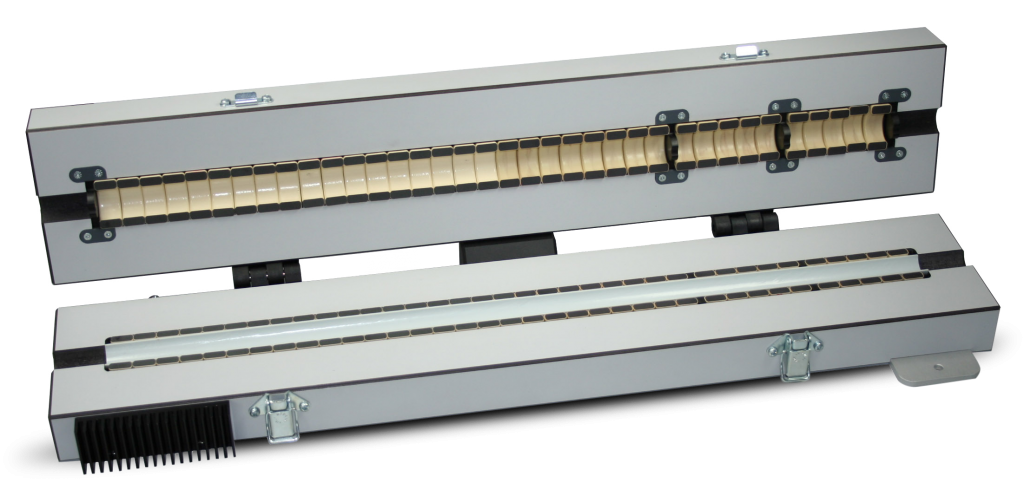
| Technical Specifications | EMCL-20 | EMCL-35 |
| Frequency range | 10 kHz-1000MHz | 10 kHz-1000MHz |
| Nominal impedance | 50Ω | 50Ω |
| Connector | N-type female | N-type female |
| Maximum input level | EMCL-20 | EMCL-35 |
| 0.15 MHz – 100 MHz | 100W, 15 min. | 100W, 15 min. |
| 100 MHz – 230 MHz | 100W, 5 min. | 100W, 5 min. |
| 230 MHz – 1000 MHz | 50W, 3 min. | 50W, 3 min. |
| Cable diameter | <20mm | <37 |
| Weight | 7 kg | 14 kg |
| Dimension (LxWxD) | 655 x 120 x 80 mm | 666 x 135 x 120 mm |
Features
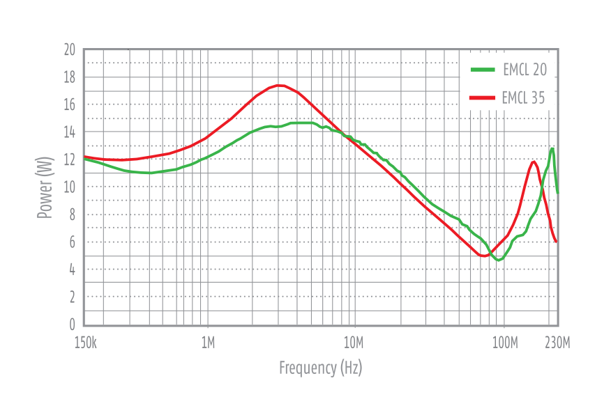
Measured amplifier output power to obtain a rest level of 10 V. 6 dB attenuator and 80% amplitude modulation depth are taken into account.
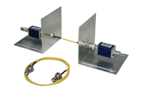
Calibration unit of EMCL (included as standard)
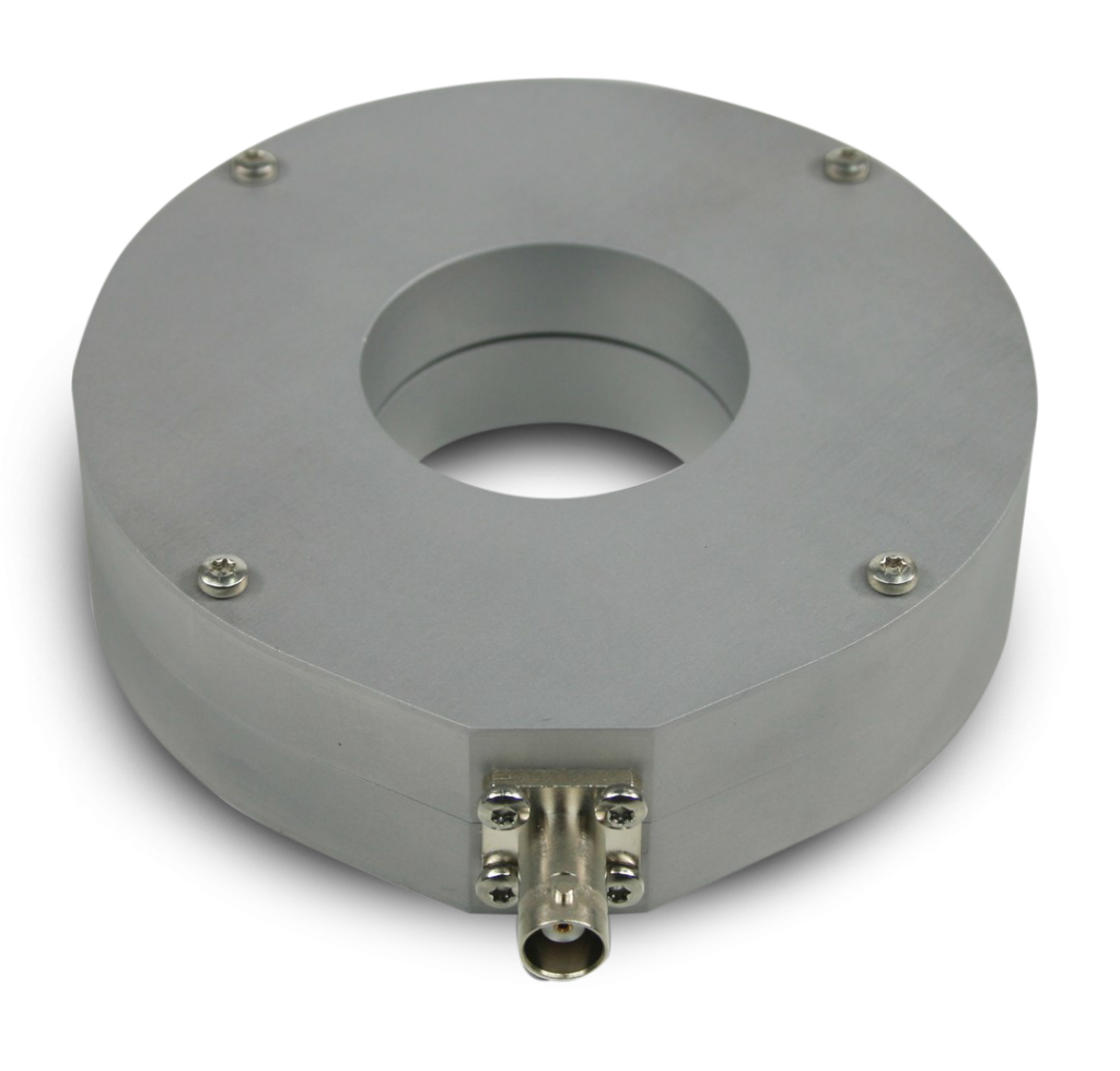
Bulk Current Injection Probe
The Bulk Current Injection Probe is used to inject RF-current into cables of electrical equipment to test the susceptibility against radiated electromagnetic energy.
It was designed to meet the specifications of ISO 11452-4:2005 and IEC 61000-4-6 standards for automotive BCI testing with secondary currents of 300 mA and more.
The probe can be easily clamped around test conductors and supports cable harness diameters up to 40 mm diameter.
Features
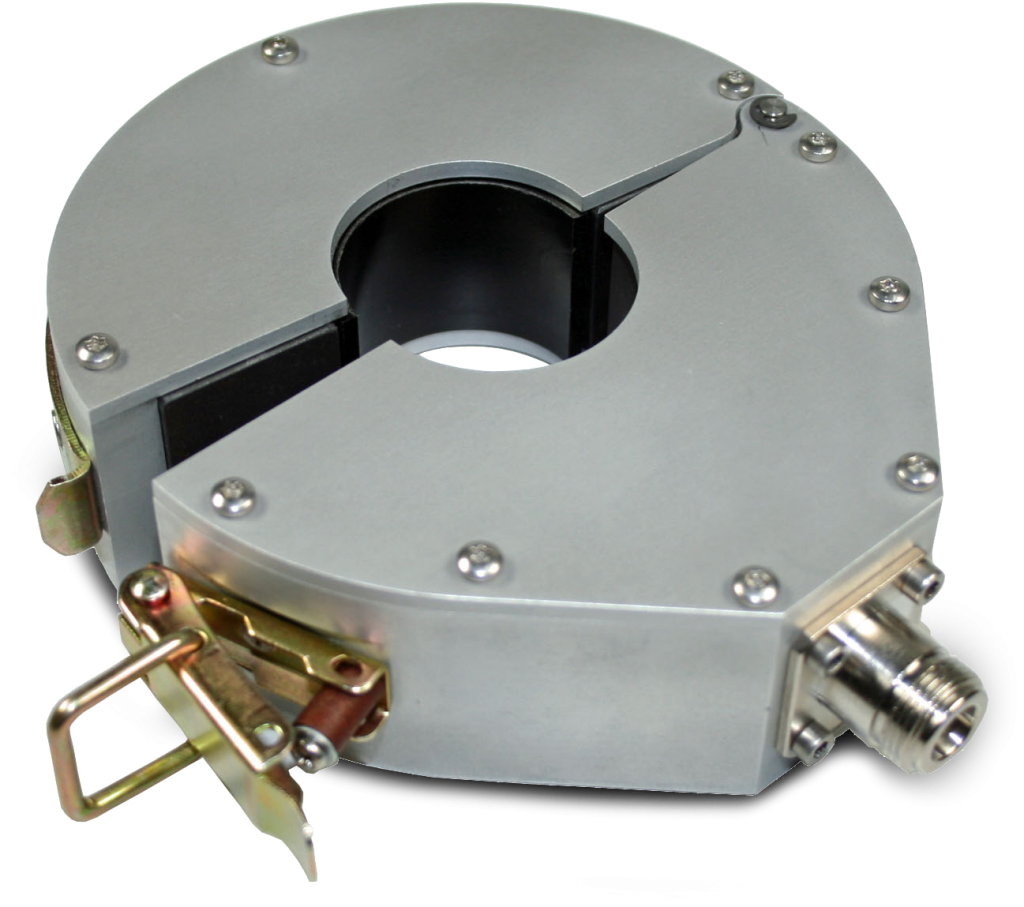
| Technical Specifications | BCI-Probe |
| Frequency range | 4 kHz – 400 MHz |
| Input Connector | Type N Female |
| Inner diameter | 120 mm |
| Outer Diameter | 40 mm |
| Width | 40 mm |
| Max. core temperature | 90 °C |
| Turns Ratio | 1:1 |
| Primary inductance | 5.1 μH @ 100 kHz |
| Ambient temperature | 0 to 40 °C |
| Fastening | 1 Clip |
| Input Power rating until core temperature is 90 °C* |
90 min @ 70 W (48.45 dBm) 45 min @ 100 W (50 dBm) |
*higher input power possible for shorter duration. Control via integrated temperature sensor.
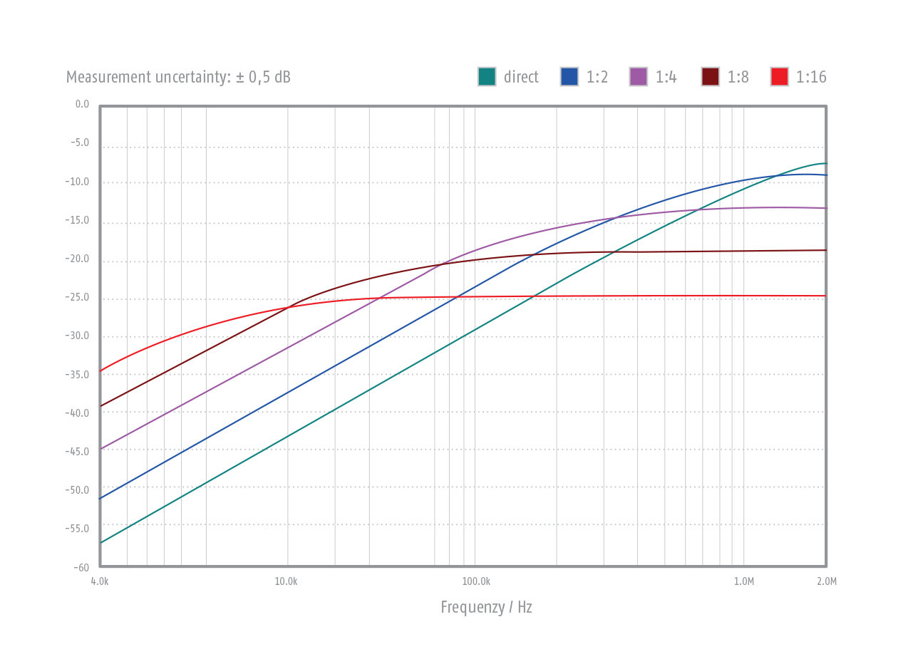
Insertin loss when using the matching transformer MT-1. The selection of the ration in dependence of the frequency can be optimized by automatic software control via LAN or UB-interface.
Bulk Current Monitoring Probe
The Current Monitoring probes may be used whenever RF current measurements are required. Current measurements are made by placing a current carrying conductor within the “sensing” window of the probe and measuring the probe’s output voltage with an RF detector. Calibration of the probe permits the conversion of the voltages measured to current. Current measurements can be made over the frequency range shown in the transfer impedance curve furnished with each probe. There is virtually no loading of the circuit and the technique permits normal operation of the device under test during measurements. The MP-50 can be used for the procedure for clamp injection when the common- mode impedance requirements cannot be met given in chapter 7.4 of IEC/EN 61000-4-6 „Immunity to conducted disturbances, induced by radio frequency fields”. The MP-50 can also be used as current monitor for BCI testing as per ISO11452-4, RTCA/DO-160 section 20, MIL-STD-461 and various automotive standards.
Features
| Technical Specifications | MP-50 |
| Frequency range | 10 kHz – 400 MHz |
| Insertion impedance | < 2,5 Ohm |
| Cable diameter | < 46 mm |
| Signal output | BNC socket |
| Max signal current (10 kHz–400 MHz) | 1A |
| Dimensions | Outer diameter 115 mm Thickness 30mm Overall length 136mm |
| Weight | 0,55 kg |
Immunity to conducted, differential mode disturbances in the frequency range 0Hz to 150 kHz
-
IEC / EN 61000-4-16
-
IEC/EN 61000-4-19
-
IEC/EN 61543
Testing devices:
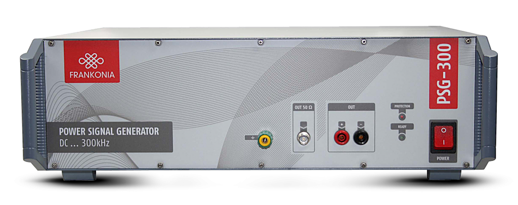
Power Signal Generator (PSG) & Isolation Transformers (IT-x)
The PSG-300 contains a linear precision power amplifier with a wide bandwidth (DC-300 kHz), suitable for all applications concerning fast alternating signals at high output power. The built in generator provides sine, square and triangle waves. Communication between PSG-300 and PC is via USB connection. The application software is suited for general power generator applications and for immunity tests according to IEC/EN 61000-4-16 as well as to IEC/EN 61543. Short term tests are enabled by phase controlled switching of an external power source (optional). The PSG-300 is equipped with a silent, temperature-controlled fan. Internal safeguards protect the amplifier from overheating and high power dissipation. They also assure protection against short-circuits and overload.
The number one choice for all applications with the need for fast and powerful signals, e. g.:
Features
| Technical specifications | PSG-300 | PSG-300A |
| Amplifier | ||
| Power bandwidth | DC – 200 kHz | |
| Slew rate | 100 V/μs | |
| Offset | ±1 mV (±0.1 mV/°C) | |
| Gain | 10 ±0.1 % (±0.01 %/°C) | |
| Output voltage | 50 Veff / ±75 Vpeak | |
| Output current | 5 Aeff / ±7.5 Apeak | 16 Aeff / ±23 Apeak |
| Power output | 250 W | 800 W |
| Distortion | < 0.10% | |
| Input impedance | 100 k Ω | |
| Max. input voltage | 80 V (cont.), 100 V (< 1 min) | |
| Noise (10 Hz – 1 MHz, input: 50 ohm) | 0.5 mVeff | |
| Output connector | 4 mm MC | |
| Output connector 50 ohm | BNC | |
| Generator | ||
| Frequency range | DC, 0.05 Hz – 300 kHz | |
| Frequency resolution | 0.05 Hz | |
| Frequency accuracy | ± 20 ppm | |
| Waveform | Sine, square, triangle | |
| External generator input | BNC | |
| General data | ||
| Remote control | USB connector | |
| Dimension (LxWxD) | 448,9×132.55×435.50mm | 448.90 x 177 x 585.50 mm |
| Weight | approx. 14 kg | approx. 30 kg |
| Technical specifications | PSG-300 | PSG-300A |
| Options | ||
| PSG-E300 | External power source for short term test 300V@DC, 162/3Hz, 50Hz, 60Hz | |
| PSG-EXT | Input connector for phase controlled switching of external power source | |
Disturbances shall not be coupled into any support instruments. This requires decoupling of the lines. In many cases isolation transformers are used for decoupling. We offer a wide range from 6A/1-phase to 20A/3.phase. All isolation transformers are compliant to IEC/EN 61000-4-16.
| Technical specifications | IT-6 | IT-16 | IT-20 |
| Voltage | 230 V | 230 V | 230 V |
| Current | 6 A | 16 A | 20 A |
| Phase | 1-phase | 1-phase | 1-phase |
| Dimensions (W x D x H) | 330x230x111 mm | 400x310x181 mm | 400x310x181 mm |
| Weight | 18 kg | 34 kg | 45 kg |
Coupling / Decoupling Networks
Immunity tests according to IEC/EN require coupling of RF disturbance voltages into any conducting cable of an EUT. Furthermore these disturbances should not be coupled into any further equipment so that a decoupling path to any auxiliary equipment is provided. We offer a wide range of CDNs for different types of interconnected lines which are fully calibrated for the frequency range from 150kHz to 230MHz. The following CDNs are available: M-, AF-, S-, T-, RJ, USB-types. Almost any network can be assambled on customer’s requests. Guidance for selecting the appropriate CDN is given in the following table:
| Type | Interconnected lines |
| M1, M2, M3, M4, M5, M2+M3 | Unscreened supply (mains) |
| AF2, AF4, AF5, AF6, AF8 | Unscreened nonbalanced lines |
| S1, S2, S4, S8, S9, S15, S25, S36 | Screened lines |
| T2, T4, T8 | Unscreened balanced lines |
| RJ11, RJ45 | Unscreened data lines |
| RJ11/S, RJ45/S, USB | Screened data lines |
Calibration:
To calibrate a CDN an adaptor, a fastening angle and 50 Ω / 150 Ω adaptor are required. Fastening angle and 50 Ω / 150 Ω adaptor should be ordered for the first CDN. For each following CDN only the specific adaptor has to be ordered.
Test procedure with Coupling/Decoupling (CDNs) Networks acc. to IEC/EN 61000-4-6:
Set-up for level setting at the EUT-port of coupling and decoupling devices:
1. The test generator (RF-out) shall be connected to the RF-input port of the coupling device via the 6dB-attenuator.
2. The EUT port of the coupling device shall be connected in common-mode through the 150 Ω to 50 Ω adaptor to the RF-Voltmeters (calibration).
3. The AE-port shall be loaded in common-mode with a 150 Ω to 50 Ω adaptor, terminated with 50 Ω.
With direct injection to screened cable (CDN S-types), the 150 Ω load at the AE-port is not required as the screen will be connected to the ground reference plane at the AE-port side.
Although the 150 Ω load at the AE-port is mandatory with CDN T-, AF- and M-types calibration data are identical with the AE-port open or short. This is because a capacitor is connected to ground at the AEport side, which leads to a RF-short-circuit similar to the CDN S-types. This means that even with CDN M-, AF- and T-types the 150 Ω load at the AE-port is not required.
Universal Coupling Network
As described in IEC/EN 61000-4-16 at the frequency of the electrical power supply (either DC, 16 2/3 Hz, 50 Hz or 60 Hz) the test stimuli are applied as both continuous and short-duration disturbances. Otherwise, over the frequency range 15 Hz to 150 kHz, the test stimuli are applied as continuous disturbances only. The normal duration for short duration disturbances at the electricity supply frequency is one second. The M2345/32-16 is a multifunctional coupling network for test levels up to ±300 V in connection with test generators MTS-800, PSG-300 and PSG-E300. In this case the M2345/32-16 is remote controlled via the application software of the test generators. Otherwise the coupling network may be front panel operated as a stand-alone device. The M2345/32-16 operates as a M2, M3, M4 or M5 coupling network. The selection can be made by a rotary switch. The coupling capacitor is shorted out for the DC tests by a push-button. For automated test you may toggle between AC and DC tests via the USB-port.
Features
Power Signal Generator (PSG) & Isolation Transformers (IT-x)
MIL-STD 461, CS 101, CS 109
Test device:
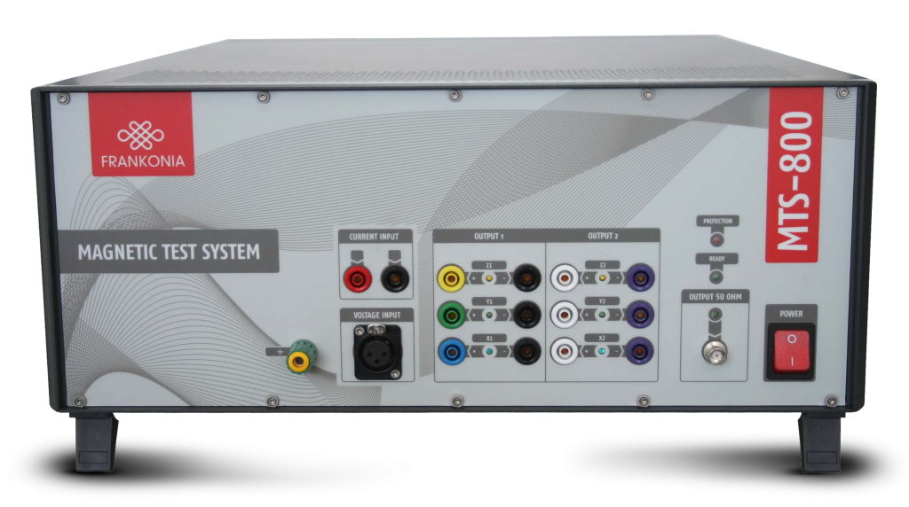
Magnetic-Field / Low-Frequency Test System
The MTS-800 is a compact test system for broadband generation and measurement of magnetic fields. Its internal components allow automatic EMC tests according to automotive standards where high field strength need to be generated or measured.
In combination with our triaxial Helmholtz coils full automated susceptibility tests are possible at magnetic field strength up to 1000 A/m for frequencies from DC to 1 kHz. Lower field strength can be generated for frequencies up to 250 kHz. Due to the triaxial setup of our Helmholtz coil major improvement in device handling is achieved because there is no need to turn an EUT during tests.
Tests and measurements are controlled by a program which will set most parameter automatically. For any relevant standard, which are fulfilled by the MTS-800, limit values are already included into the software package, although any different value can be defined by a user. After every test full reports will be created automatically. Report layout is pre-defined, though any user-defined layout is possible. High performance is guaranteed by a self-calibration
Special Features
Options
Applications
Magnetic Field Generation
MTS-800 enables a user to generate strong magnetic fields up to 1000 A/m. Even alternating fields up to 250 kHz can be generated by the magnetic test system.
Low Frequency emission and immunity tests
acc. to MIL-STD 461, CE 101, RE 101, CS 101, CS 109 and RS 101. Individual software modules and hardware accessories are available for each of these tests.
Automotive Testing
Intensive testing is required for new products which should be used in any automotive application. The MTS-800 allows fast and easy testing according to many automotive standards as described before.
Technical specifications
| Voltage input (Analyzer) | MTS-800 |
| Frequency range | DC – 250 kHz |
| Input impedance | 1 MΩ / 50 Ω switchable |
| Connector | XLR, unbalanced |
| Max. input voltage | 100 V continuous (attenuator autoset at overvoltage); 10 V at 50 Ω |
| Gain | -20/0/20 dB Preamplifier, 0/20/40 bB ADC Amplifier; Self-calibration with ultra stable on-board reference |
| Current input | MTS-800 |
| Frequency range | DC – 250 kHz |
| Shunts | 10 mΩ / 1 Ω / 100 Ω |
| Max. input current | 20 A continuous (overload protection); 1 Ω and 100 Ω shunt are protected by an additional 1.5 A fuse |
| Connector | 4 mm safety jack (+, -) measurement via insulation amplifier or input jacks |
| Measurement range | 20 A, 10 A, 1 A, 100 mA, 10 mA, 1 mA automatic offset and gain; Self-calibration with ultra stable on-board reference |
| AD converter | MTS-800 |
| Resolution | 16 Bit |
| Sampling rate | 1.25 MSPS |
| Aliasingfilter | 0.01 dB Tschebyscheff filter, fg = 260 kHz; filter may be switched off |
| Generator | MTS-800 |
| Frequency range | DC – 250 kHz |
| Output impedance | 50 Ω |
| Connector | BNC, unbalanced |
| Signal | Sine wave / triangular / square wave / DC |
| Amplitude | 0 to 10 VAC, -10 V to +10 VDC |
| Resolution | 12 Bit (2.5 mV), Switchable – 20 dB Attenuator; Self-calibration with ultra stable on-board reference |
| Amplifier | MTS-800 |
| Frequency range | DC – 1 MHz |
| Connector | 4 mm safety jacks (output); BNC, unbalanced (input) |
| Current | 16 Arms |
| Voltage | 50 Vrms / 75 VDC |
| Distortion (DC-100 kHz, load ≥ 4 Ω) | < 0.10 % |
| General data | MTS-800 |
| EUT control / Connector | 9-pin Sub-D; RS232 |
| Connection to Computer | USB |
| Temperature range | 0 to 40 °C |
| Warm-up time | 15 min. |
| Housing | 19”-Subrack or desktop case |
| Dimensions (WxHxD) | 449 x 177 x 580 mm |
| Weight (shipping) | approx. 40 kg (net 34 kg) |
| Gain | 10 ±0.1% (±0.01% / °C) |
Features
Automatic Testing Capabilities
Full compliance with several immunity test as ISO 11452-8, MIL-STD-461 RS101, CS101, CS109, IEC/EN 55103-2, IEC/EN 61000-4-8, SAE J1113-2, SAE J1113-22, Ford ES-XW7T-1A278-AC, GM W3097, PSA B21 7110, Renault 36-00-808, DC-11224, DC 10614 and similar standards. Furthermore the MTS-800 allows emission measurements according to MILSTD- 461E/F RE101, CE101 and IEC/EN 55103-1.
Software
Any function is controlled via a software which also guide the user through any test or measurement. Adaptation of signal strength or measurement graphs are possible at any stage. User defined signals complement the usage for fast and reliable tests. The software is written in LabVIEW which guarantees stable and fast performance on any Microsoft® Windows platform.
Components
MTS-800 consists of 3 independent modules: a signal generator (DC – 250 kHz), a power amplifier (800 W output maximum, DC –1MHz bandwidth) and spectrum analyzer (16 Bit, 1 MSPS sampling rate). All modules can be used as stand-alone units.
Self-calibration
Using an ultra-stable voltage source self-calibration correction values are stored in an internal EEPROM. Any voltage signal or voltage measurement device is calibrated at a self-calibration process automatically in about a minute.
Accessories
Frankonia provides also many different coils and loop sensor which are ideally suited for the described tests. Any additional equipment is ready to use without a need for recalibration. Not only our own equipment can be used with the MTS-800, but also user defined coils. A calibration mode is included in the software to complement the magnetic test system with any further equipment.
Further features and possibilities
Helmholtz Coils
Several Helmholtz coils are available for susceptibility tests. We also offer tri-axial Helmholtz coils which are suitable for MTS-800. To achieve 1000 A/m at 1 kHz, it is absolute necessary to use our Helmholtz coils and an optional compensation board.
| Coil Type | Technical specifications |
| HCST_50/28_TAP (1) | Tapped triaxial Helmholtz coil for immunity tests |
| HCS_50/28_TAP (2) | Tapped single axis Helmholtz coil for immunity tests |
| Max. current | Designed for the generation of magnetic fields with field strength > 1000 A/m |
| HCS_125/75_TAP | Tapped single axis Helmholtz coil for immunity tests according to IEC / EN 55103 |
Loop Sensors / Radiating Loops
For immunity tests we offer radiating loops which are necessary to generate magnetic fields. The required loop sensors for measuring emission can also be ordered.
| Coil Type | Technical specifications |
| RL_120 (3) | 120 mm radiating loop according to MIL-STD-461 |
| LS_040 (4) | Electrostatically shielded loop sensor according to MIL-STD-461 |
| LS_133 | Electrostatically shielded loop sensor according to MIL-STD-461 |
| RS_133 | Electrostatically shielded loop sensor according to IEC/EN 55103-1/2 |
| Can be used as radiating loop and loop sensor. | |
Coupling Transformer
MIL-STD-461 CS 101 requires a coupling transformer for conducted susceptibility tests. Frankonia has developed a coupling transformer which meets all requirements. Due to direct coupling to voltage mains, the coupling transormer has an additional differential amplifier for common mode rejection of the AC mains. Using the coupling transformer without this amplifier can destroy any measurement instrument due to overvoltage.
Testing equipment acc. to IEC/EN 55103-2
IEN/EN 55103-2 requires certain immunity tests for frequencies from 50 Hz to 10 KHz. The following test equipment fulfills all requirements according to IEC/EN 55103-2, annex B.
Control Panel
The software starts with the generator/amplifier control panel. This window allows basic settings of generator and amplifier.
Standard generation window
Open the Magnetic field generation window for susceptibility tests according to predefined standards.
Magnetic field continuous generation window
Open the continuous generation window for long term magnetic field test.
Example standard file
Edit a predefined standard or create a new one. Load, save and print data.
Measurement results
Open the Magnetic field measurement window for spectrum analyzer measurements. Perform a single or continuous measurement. Perform test according to predefined standards.
Current transducer incl. correction network
Calibration network
Common mode test adapter
Accessories selecting table
| Test equipment MIL-STD 461 | Recommended Model | CE101 | CS101 | CS109 | RE101 | RS101 |
| Measurement receiver | MTS-800 | • | • | • | • | |
| Current probe | Any commercially available model | • | • | • | ||
| Signal generator | MTS-800 | • | • | • | • | • |
| Power amplifier | MTS-800 | • | • | • | ||
| Data recording device | MTS-800 | • | • | |||
| Oscilloscope | MTS-800 | • | • | |||
| Coupling transformer | CT_2.5/50 AC | • • | ||||
| Isolation transformer | IT-6/-16/-20/ | • | • | |||
| LISNs | Any commercially available model | • • • • | ||||
| Radiating loop 12cm | RL_120 | • | ||||
| Loop sensor 4cm | LS_040 | • | ||||
| Loop sensor 13.3cm | LS_133 | • | ||||
| Ohmmeter | Any commercially available model | • | ||||
Standards
| CE101 | Conducted Emission, Power Leads, 30 Hz to 10 kHz |
| CS101 | Conducted Susceptibility, Power Lead, 30 Hz to 150 kHz |
| CS109 | Conducted Susceptibility, Structure Current, 60 Hz to 100 kHz |
| RE101 | Radiated Emission, Magnetic Field, 30 Hz to 100 kHz |
| RS101 | Radiated Susceptibility, Magnetic Field, 30 Hz to 100 kHz |