Emission measurements
EMI-Receiver
Antennas
Accessories
Broadband pre-Amplifier
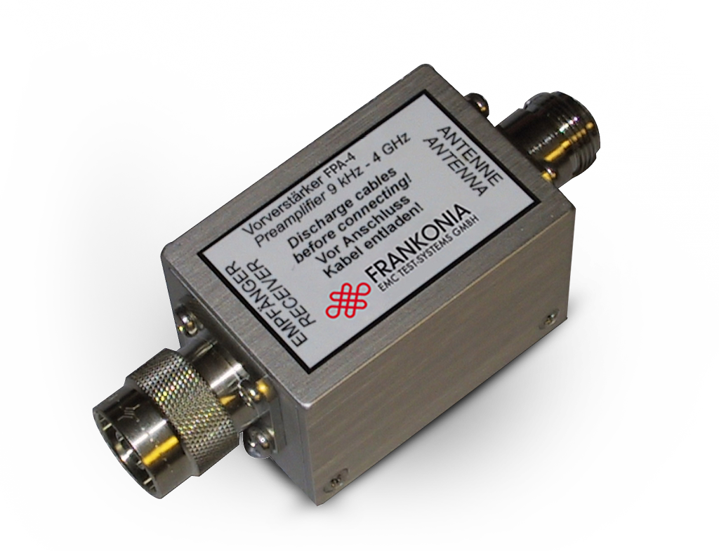
The FPA-x is a general purpose broadband pre-amplifier with high gain and low internal noise. The wide frequency range up to 2/6 GHz allows measurements acc. CISPR 22. Due to the high gain and the low noise figure the system noise is nearly independent of the other components including cable and receiver. These features make the FPA-x very useful for the measurement of very low limits, as required for CISPR 25. In this case it will be connected directly to the antenna. The amplifiers FPA-2 and FPA-6A are ESD protected to prevent defects by unintentional electrostatic discharge. The FPA offers a frequency range from 9 kHz to 6 GHz. For technical reasons it cannot be ESD-protected and special care is necessary. Nevertheless pre-amplifiers are generally ESD-sensitive devices, therefore it is very important to discharge coaxial cables before being connected. This is an essential precaution to protect the extremely small semiconductor structures operating in the microwave frequency range.
It must be noted that the use of pre-amplifier is generally not recommended for the measurement of impulsive signals. Such broadband noise is typical for many EMC measurements. This means that any broadband pre-amplifier is not suitable for EMC measurement of a broadband pulse spectrum. The FPA-x has an aluminum enclosure and uses N-Type flange connectors. A standard wall plug supply with +12 VDC output can be used. A suitable power supply for 230 V with Schuko socket is included in the delivery. The use of switching power supplies is not recommendable as they may cause higher levels of interference. An internal protection circuit slows down the rising and falling edge of the power supply voltage to prevent internal components and the receiver from being damaged by voltage spikes. 12 V auxiliary supplies from receivers and analyzers or batteries are also suitable if they can provide a continuous current of 0.14 A.

| Technical specifications | FPA-2 | FPA-6A | FPA-6B |
| Frequency range | 9 kHz – 2 GHz | 10 MHz – 6 GHz | 9 kHz – 6 GHz |
| Noise figure | 2.5 dB (1.0 GHz) | 2.5 dB (1.0 GHz) | 2.5 dB (1.0 GHz) |
| Gain | + 30 dB | + 28 dB | + 28 dB |
| Amplitude flatness | < ± 3 dB | < ± 3 dB | < ± 3 dB |
| 1 dB compression point at input | ≥ -20 dBm (87 dBμV) | ≥ -18 dBm (89 dBμV) | > 100 dBμV |
| Impedance | 50 Ω | 50 Ω | 50 Ω |
| VSWR input / output | < 2:1 | < 2:1 | < 2:1 |
| ESD protection | yes | yes | yes |
| Power supply | + 12 V (± 2 V) | + 12 V (± 2 V) | + 12 V (± 2 V) |
| Current consumption | < 120 mA | < 130 mA | < 120 mA |
| Dimensions | 82 x 38 x 27 mm | 82 x 37 x 27 mm | 88 x 41 x 27 mm |
| Weight | 150 g | 141 g | 160 g |
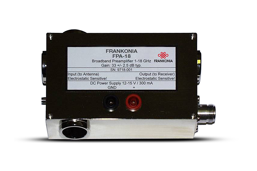
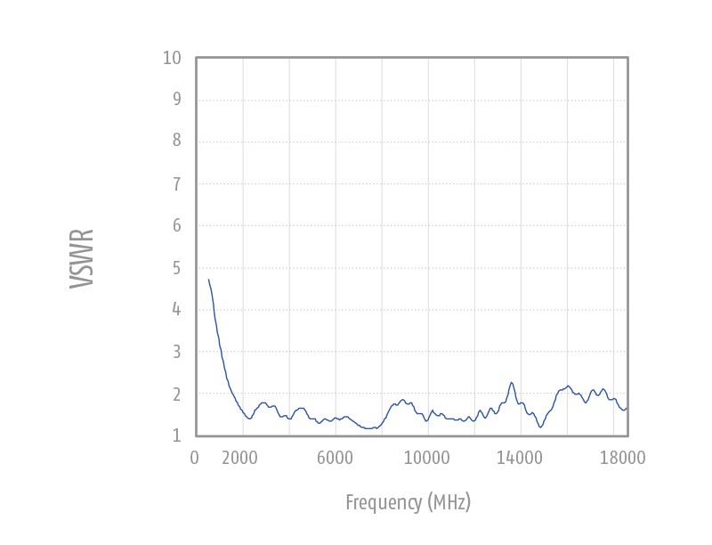
Low noise low power wideband amplifier for increasing sensitivity at field strength measurements and for general attenuation measurements up to 18 GHz. A power supply with 12 V / 300 mA DC (e.g. optional AC/DC adap- tor, laboratory power supply, rechargeable battery) is required for operation. In- and output of the broadband amplifier are sensitive to electrostatic dis- charge. Therefore some precaution (discharging coaxial cables and persons) is required before touching the amplifier. The amplifier input comes with an SMA- female connector.
A coaxial microwave cable of 0.5 m length is sup- plied to connect the antenna with the amplifier. The cable is equipped with N-male and SMAmale connectors. Usually the amplifier should be installed very close to the antenna. The amplifier housing is equipped with rubber pads for placement on horizontal sur- faces. Further there are 22 mm holes in the housing to accept the mounting tube of Frankonia antennas. The antenna mounting tube is usually oriented horizontally with the N-female output of the amplifier facing to ground. This avoids undesired bending of the coaxial cable.
| Technical specifications | FPA-18 |
| Nominal Frequency range | 1 GHz – 18 GHz |
| Usable Frequency range | 0.5 GHz – 20 GHz |
| Connectors | 50 Ω N / SMA |
| Fixation | Ø 22 mm tube |
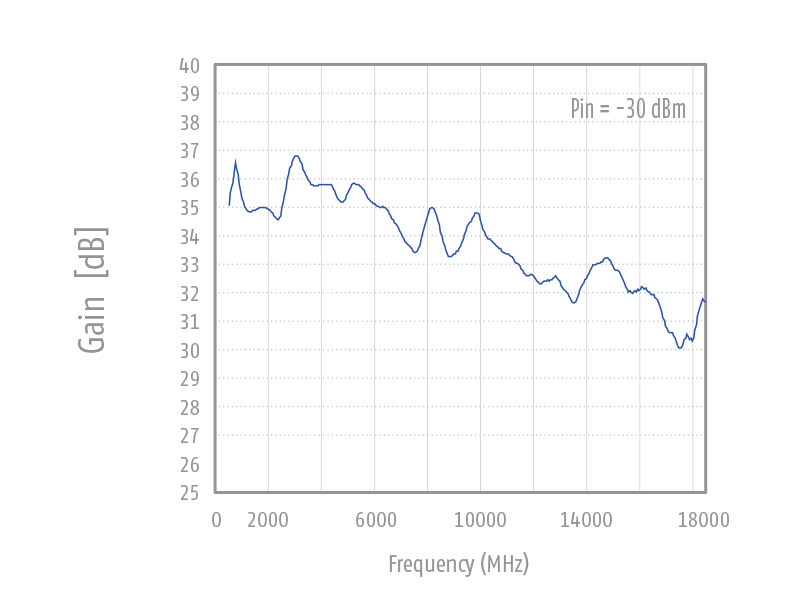
| Gain | typ. 33 dB ± 2.5 dB |
| Gain min. | > 28 dB |
| Max. input power | -10 dBm (97 dBμV) |
| SWR typ. | < 2 |
| Noise figure | 2 dB |
| Supply voltage | 12V – 15 V / DC |
| Current consumption | 250 – 300 mA |
| Power supply via female banana sockets | 4mm |
| Weight | 600 g |
| Dimensions (W x L x D) in mm | 142 x 90 x 48 |
Low noise low power wideband amplifier for increasing sensitivity at field strength measurements and for general attenuation measurements up to 26.5 GHz. A power supply with 12 V / 300 mA DC (e.g. optional AC/DC adaptor, laboratory power supply, rechargeable battery) is required for operation. In- and output of the broadband amplifier are sensitive to electrostatic discharge.
Therefore some precaution (discharging coaxial cables and persons) is required before touching the amplifier. The amplifier input comes with SMA female connectors. A coaxial microwave cable of 0.5 m length is supplied to connect the antenna with the amplifier. The cable is equipped with SMA-male connectors. The amplifier is equipped with a female 3/8” camera thread to be connected to a mast, e.g. to FSM-1.6. The antenna itself is mounted with another 3/8” screw at the amplifier base. The polarization swivel can easily be achieved within seconds by a further screw in 45° steps using fixing bolts for indexing.
It is very important to avoid bending and torsion of the microwave cable, other- wise persistent damage may be a result. Therefore we recommend to mount the antenna in a way that the antenna connector points into the opposite direction as the RF-input of the amplifier. This allows a smooth routing the microwave cable with a wide bending radius.
| Technical specifications | FPA-26 |
| Nominal Frequency range | 18 GHz – 26.5 GHz |
| Usable Frequency range | 12 GHz – 28 GHz |
| Connectors | 50 Ω SMA |
| Mounting thread | 3/8″ |
| Gain | typ. 33 dB ± 2 dB |
| Gain min. | 30 dB |
| Max. input power | -20 dBm (87 dBμV) |
| SWR typ. | < 2 |
| Noise figure | 3.5 dB |
| Supply voltage | 12V – 15 V / DC |
| Current consumption | 250 – 300 mA |
| Power supply via female banana sockets | 4mm |
| Weight | 400 g |
| Dimensions (W x L x D) in mm | 210 x 100 x 60 |
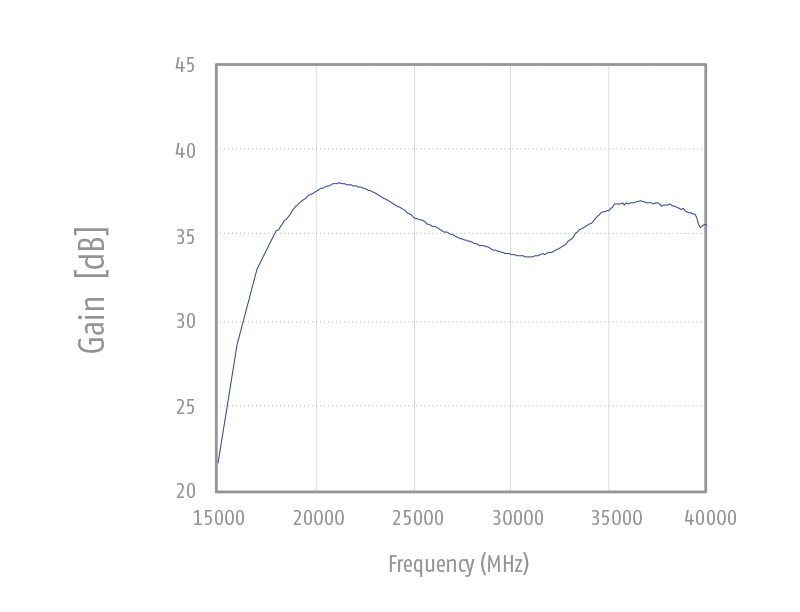
Low noise low power wideband amplifier for increasing sensitivity at field strength measurements and for general attenuation measurements up to 26.5 GHz. A power supply with 12 V / 300 mA DC (e.g. optional AC/DC adaptor, laboratory power supply, rechargeable battery) is required for operation. In- and output of the broadband amplifier are sensitive to electrostatic discharge.
Therefore some precaution (discharging coaxial cables and persons) is required before touching the amplifier. The amplifier input comes with SMA female connectors. A coaxial microwave cable of 0.5 m length is supplied to connect the antenna with the amplifier. The cable is equipped with SMA-male connectors. The amplifier is equipped with a female 3/8” camera thread to be connected to a mast, e.g. to FSM-1.6. The antenna itself is mounted with another 3/8” screw at the amplifier base. The polarization swivel can easily be achieved within seconds by a further screw in 45° steps using fixing bolts for indexing.
It is very important to avoid bending and torsion of the microwave cable, other- wise persistent damage may be a result. Therefore we recommend to mount the antenna in a way that the antenna connector points into the opposite direction as the RF-input of the amplifier. This allows a smooth routing the microwave cable with a wide bending radius.
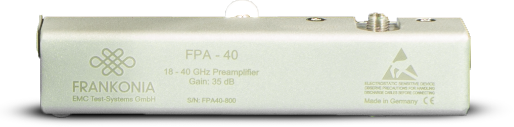
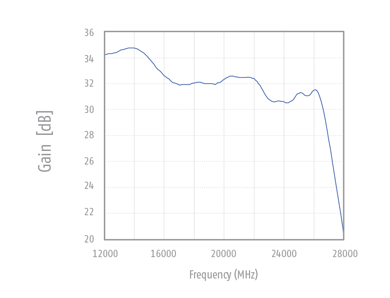
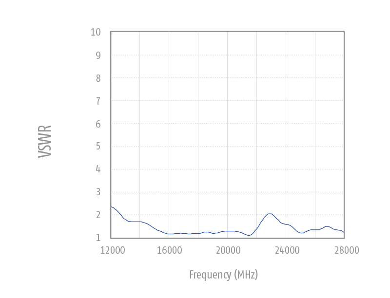
| Technical specifications | FPA-40 |
| Nominal Frequency range | 18 GHz – 40 GHz |
| Usable Frequency range | 18 GHz – 40 GHz |
| Connectors | 50 Ω 2.92 |
| Fixation | Ø 22 mm tube |
| Gain | typ. 35 dB ± 4 dB |
| Gain min. | 30 dB |
| Max. input power | -20 dBm (87 dBμV) |
| SWR typ. | < 2.6 |
| Noise figure | 5.5 dB |
| Power supply 1 | 15 V / 600 mA DC |
| Power supply 2 | -(8 … 15) V / -100 mA DC |
| Power supply via female banana sockets | 4mm |
| Weight: | 860 g |
| Dimensions (W x L x D) in mm | 370 x 95 x 65 |

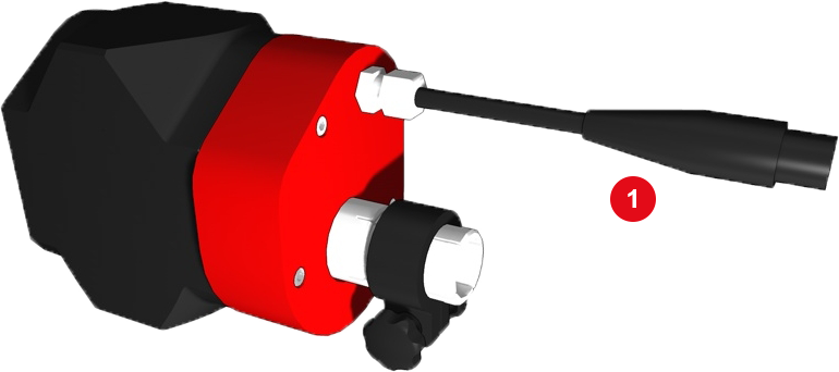
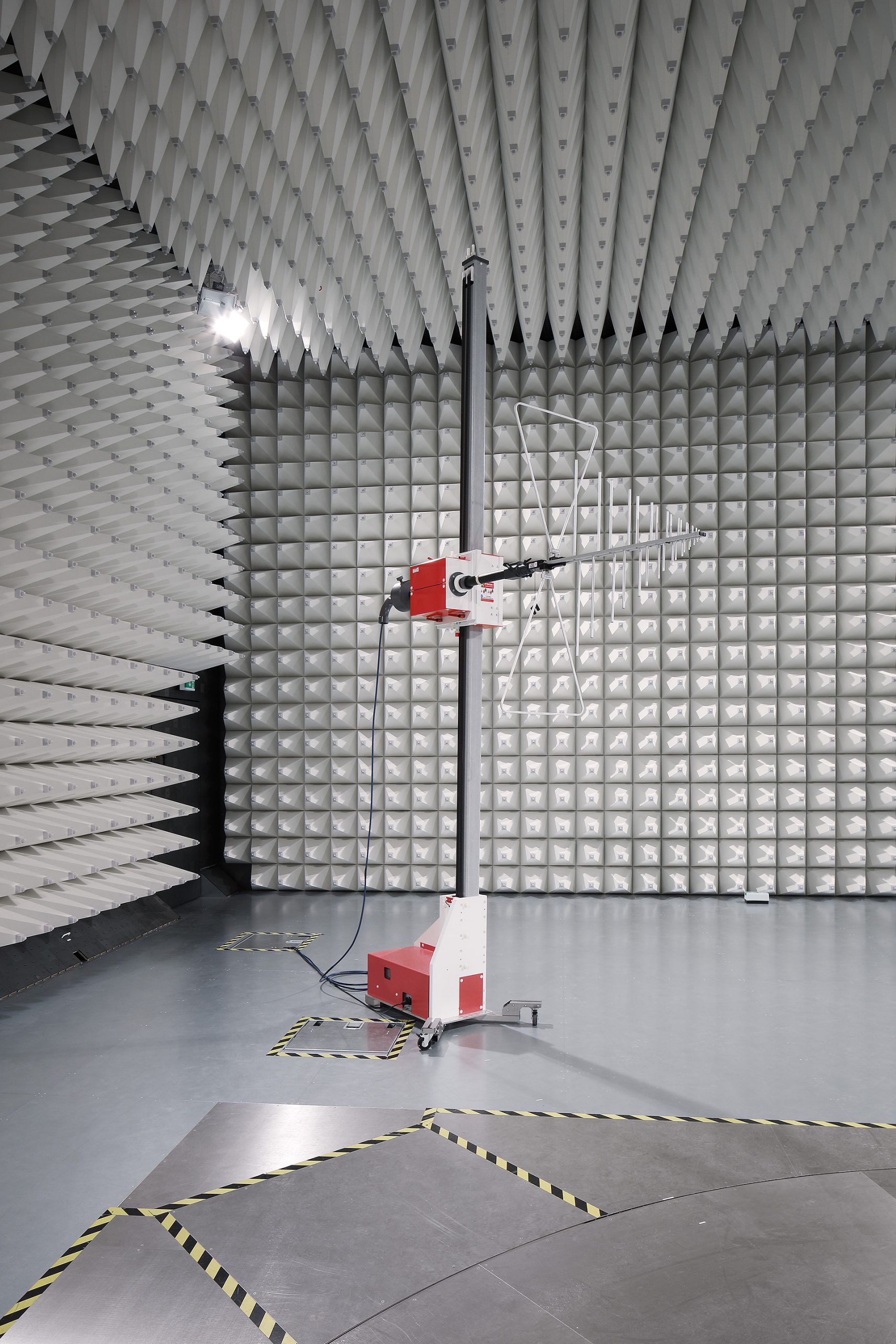
Electrical Polarization Switch
The polarization device FPD-01 (1) is designed for the polarization of antennas. The maximum weight of antennas is 5 kg, slewing range 0° – 90°. The FDP-01 polarization unit has an antenna tube of 22mm, which is equipped with a clap ring for easy and safe installation of antennas. On the side a 3/8-16 UNC thread is foreseen for the installation of a stand.
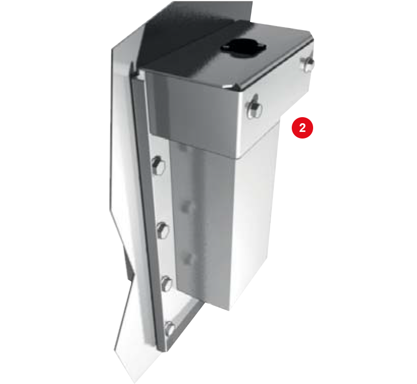
The control is effected with the controller FC06-24V. The control signal is feed through the shielded wall via an EMC filter that is mounted on the carrying unit. (2)
| Technical specifications | FPD-01 |
| Polarization electric | 0° – 90° |
| Polarization time | ca. 5 sec |
| Polarization accuracy | 0.2° |
| Dimensions (W x L x D) in mm | 200 x 110 x 90 |
| Weight | 2.5 kg |
| Antenna weight | Max. 5 kg, depending on gravity, size and used connection adapter of the antenna |
| Mast mount | 3/8″ female |
| Antenna tube | Ø 22mm ± 0,1mm |
| Voltage | 24V DC |
| Connection | XLR male |
| Connection to tripod | Thread 3/8-16 UNC |
| Technical data feedthrough | FPD-01 |
| Dimensions (W x L x D) in mm | 350 x 190 x 166 |
| Weight | 6 kg |
| Connection | XLR male to XLR female |
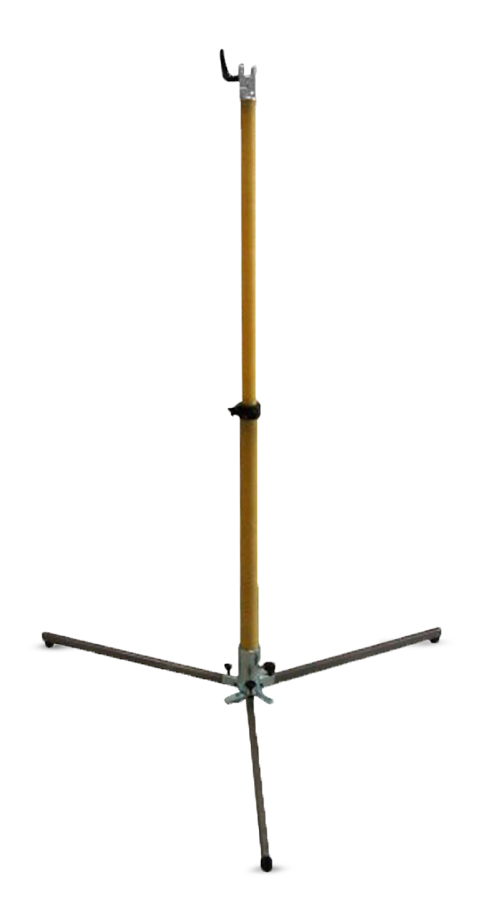
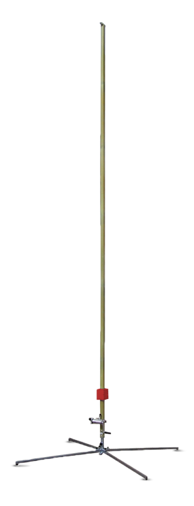
Manual Antenna Masts
The height level of the double telescopic antenna masts FSM-1.6 and FSM-2.0 can be manually adjusted from 0.9 / 1.2 m to 1.6 / 2.0 m (depending on the model). The continuous height setting is made within a few seconds. In order to avoid unwanted reflexions the mast rods are made of fibre glass. A collapsible tripod provides a secure stand and easy adaption to uneven ground. The perpendicular mast-adjustment is simplified with a spirit level mounted at the tripod. A rotatable spider fixes the tripod-legs for easy movement within seconds by one person only. Antennas can be mounted directly on the 3/8” male thread or using adapters for double stacked antennas.
| Technical specifications | FSM-1.6 | FSM-2.0 |
| Height range | 0.9 – 1.6 m | 1.2 – 2.0 m |
| Antenna or adapter mount | 3/8″ male | 3/8″ male |
| Material mast | fibre glass | fibre glass |
| Recommended adapters | MAS / MAD | MAS / MAD |
| Weight | 6 kg | 7 kg |
| Dimensions for transport | 1.0 x 0.3 x 0.3 m | 1.2 x 0.3 x 0.3 m |
Datasheets:
The main application of FSM-4.0 are emission measurements, where frequent height scans are required. Level adjustment from 0.4 m to 4.15 m can easily be done by using the manual winch. The mast can be setup and disassembled without any tools within 2 min. The FSM-4.0 tripod is suitable for both stationary and mobile applications. Thanks to its small transport dimensions it can be stored without problems even in small cars. The antennas are mounted with their 22 mm tube directly to the support, the polariza- tion is fixed with an indexing ring for both, vertical and horizontal polarization without tools. There is no additional adapter needed to accept antennas with 22 mm tubes. Each of the three spider legs can be adjusted individually for a coarse level adjustment on uneven or inclined mounting.
| Technical specification | FSM-4.0 |
| Height scan | with manual winch |
| Height scanning range | 0.4 … 4.15 m |
| Required time for complete height scan | < 8 s |
| Required time for mast assembly | < 2 min |
| Antenna mount | 22 mm with index ring |
| Mast material | fibre glass |
| Tripod material | zinc-plated steel |
| Costed option | fibre glass |
| Maximum antenna weight | 5 kg |
| Total weight | 13 kg |
| Tripod leg circuit diameter | 02.06 m |
| Dimensions for the transport | 1.17 x 0.3 x 0.3 m |
Frankonia Antenna Masts
The FAM is Frankonia’s standard antenna mast solution compliant according to CISPR 16-1-4. For customers’ convenience, the Frankonia antenna mast are equipped with wheels and can be folded to enable easy transportation and handling. To reduce unintentional reflections, the masts are made of fiberglass and plastic materials. Any reflecting materials have been reduced to a minimum.
| Type | FAM2-4 | FAM2-6 | |
| Polarization | Electric, 0° to 90° | ||
| Polarization time | approx. 6 sec. | ||
| Polarization accuracy | 0,2° | ||
| Height scan (Electric) | 0,9-4,0m | 0,9-6,0m | |
| Height scan accuracy | ±5mm | ||
| Height scan speed | 10mm/sec to 150mm/sec (dynamic movement) | ||
| Dimensions | 1,2×0,9×4,5m | 1,2×0,9×6,5m | |
| Weight | approx. 85 kg | approx. 90 kg | |
| Power supply | 230V | ||
| Antenna weight | max. 12 kg incl. adapter | ||
| Interface | IEEE 488.2 GPIB interface with SCPI commands | ||
| Controller | FC06.1 | ||
Features
Based on the FAM antenna mast construction, the FBM boresight antenna mast is compliant with ANSI C63.4 and CISPR 16-1-4 that includes an advanced tilt function. To offer full flexibility, the tilt function can be switched off, so that the FBM operates as a standard mast. Within the tilt function, the FBM software automatically calculates the tilt angle in accordance with the antenna specific reference point, as well as distance, position and size of the EUT and monitors the complete test procedure.
| Polarization | Pneumatic, 0° to 90° |
| Polarization time | approx. 6 sec. |
| Polarization accuracy | 0,2° |
| Height scan (Electric) | 1,0-4,0m |
| Height scan accuracy | ±5mm |
| Height scan speed | 10mm/sec to 150mm/sec (dynamic movement) |
| Tilt | 0°-50° automatic adjustment |
| Tilt accuracy | ±0,5° |
| Dimensions | 1,3×0,8×4,9m |
| Weight | approx. 95 kg |
| Power supply | 230V |
| Air | 6-8 bar |
| Antenna weight |
max. 12 kg incl. adapter (normal mode) max. 8 kg incl. adapter (boresight mode) |
| Interface | IEEE 488.2 GPIB interface with SCPI commands |
| Controller | FC06.1B |
Features